Arrangement and method for loading data into a memory

Inactive Publication Date: 2008-05-29
FRANCOTYP POSTALIA
View PDF8 Cites 5 Cited by
  • Summary
  • Abstract
  • Description
  • Claims
  • Application Information

AI Technical Summary

Benefits of technology

[0010]It has been shown that a simple detection of the load state of the memory is possible even for a memory organized per sector. Through this detection and the checking of the load state of the memory of the receiver device made possible thereby, in a simple manner the number of the data packets to be transmitted to the receiver device in the load step can be limited only to the absolutely necessary extent such that, different from conventional loading procedures, it is no longer required to completely transmit the data to be loaded from the transmitter device to the receiver device after a connection termination in a (normally immediately) preceding load step. The time expenditure for the transmission is thereby significantly reduced under certain circumstances.
[0015]The successful complete loading of the data can be documented in any suitable manner. Preferably load state information identifying the successful conclusion of the load step is stored in the load step after the successful loading of the last data packet. A fast, later detection of the successful conclusion of the load step is thus made possible.
[0019]In preferred variants of the invention, different versions of the data to be loaded can be detected. It is therefore preferable to make a version comparison in the check step of the version of the current data loaded in the memory and the version of the data to be loaded into the memory, and the load step is implemented only when the version of the data to be loaded into the memory is more current than the version of the current data loaded in the memory and / or a load instruction initiating the load step exists. It is thus possible to avoid an accidental re-loading of already-loaded data.
[0025]In another variant of the invention, the respective data packet is first written into a buffer region of the memory in the load step. This has the advantage that the main function part of the firmware can then take over the communication with the transmitter device and the buffering of the data packets so that the load part of the firmware later must take over only the organization of the data and the exchange of the main function part. Although, this requires more memory space, the load part can be correspondingly simple and thus small.
[0028]The transmitter device can generate an erasure information dependent on the current load state of the memory, this erasure information directly identifying the memory sectors of the memory to be erased in the load step. The transmitter device then transmits the erasure information to the receiver device so that in the load step the corresponding memory sectors are erased dependent on the erasure information. This has the advantage that no computation capacity for the calculation of the memory sectors to be erased must be addressed in the receiver device, which normally has a limited computation capacity.
[0029]In other variants of the invention, the receiver device itself determines the memory sectors to be erased. This has the advantage that the transmitter device must have no knowledge about the type and / or composition of the memory, such that the data retention in the transmitter device is simplified or reduced or no corresponding communication in this regard must occur between the transmitter device and the receiver device.

Problems solved by technology

If such an unscheduled interruption occurs, all data typically are retransmitted between the transmitter and the receiver in a new communication, which can lead to the situation that, in particular given very unstable connections, a relatively long time is required until the complete loading of the data into the memory of the receiver is accomplished.

Method used


Image

  • Arrangement and method for loading data into a memory
  • Arrangement and method for loading data into a memory
  • Arrangement and method for loading data into a memory

Examples


Embodiment Construction

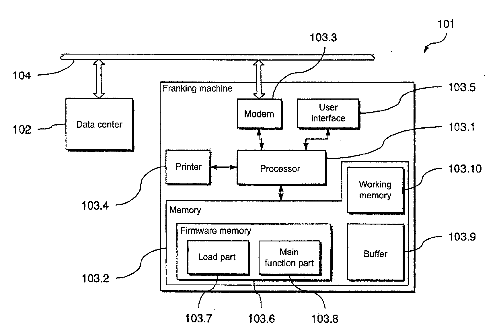
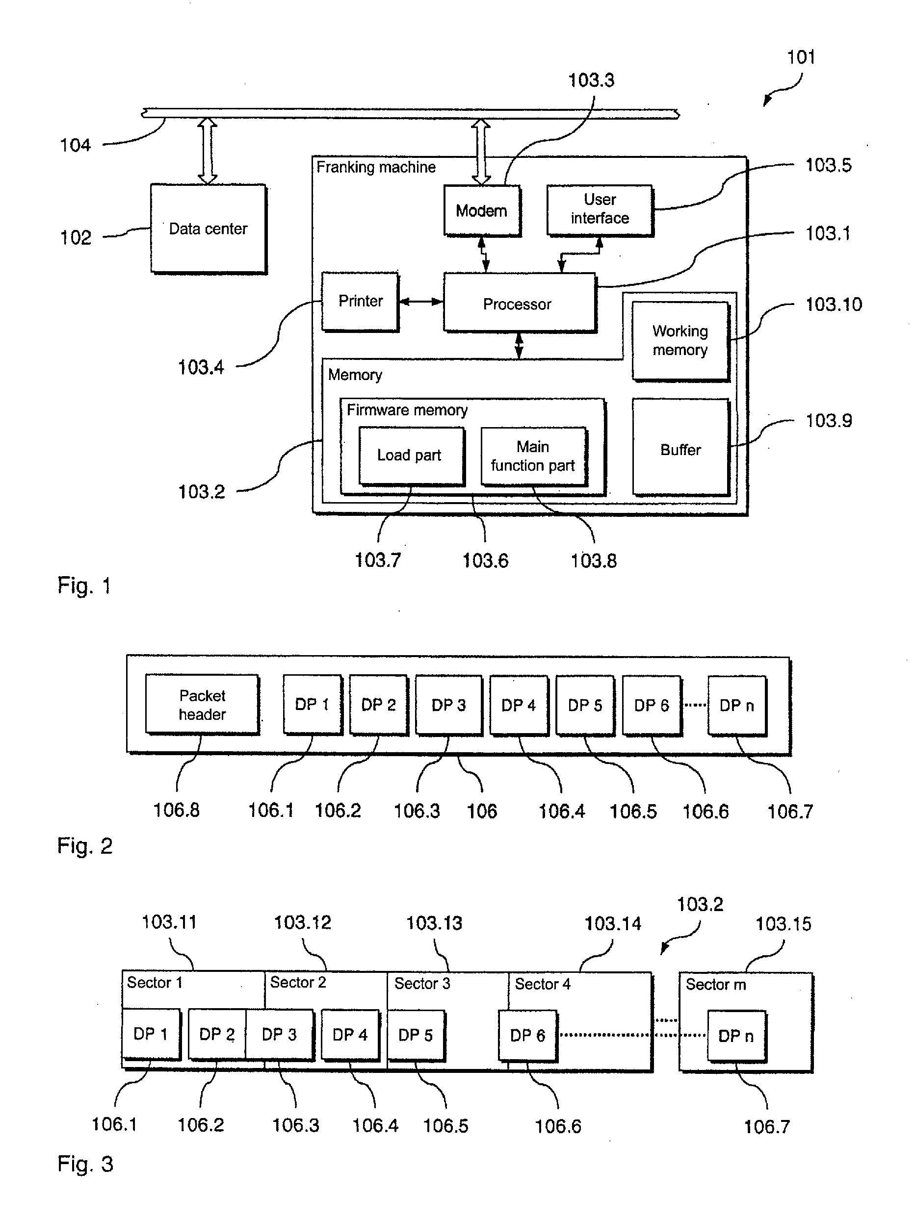
[0046]In the following, a preferred embodiment of the inventive arrangement 101 for loading of data from a transmitter device (in the form of a data center 102) into a receiver device (in the form of a franking machine 103) is described with reference to FIGS. 1 through 4B. With this preferred embodiment a preferred embodiment of the inventive method for loading of data is implemented. The franking machine 103 can be connected with the remote data center 102 via a communication network 104.

[0047]The franking machine 103 includes a processor 103.1 in the form of a microprocessor and a memory 103.2 connected therewith. The franking machine 103 can be connected with the communication network 104 (and therewith with the data center 102) via a modem 103.3 connected with the processor 103.1. Furthermore, the franking machine 103 comprises a printing device 103.4 by means of which franking imprints can be generated as well as a user interface 103.5 (for example display and keyboard) via wh...


PUM


Abstract

In a method and arrangement for loading data from a transmission device into a non-volatile memory of a receiver device that can be connected with the transmission device, the non-volatile memory being erased only sector-by-sector, the data to be loaded are divided by the transmission device into a number of data packets and at least one part of the data packets is loaded into the memory in a load step. A check step that is implemented before the current load step in which a current load state of the memory is checked, the current load state indicating whether at least a part of the data packets has already been successfully loaded into the memory in a preceding load step. The data packets to be loaded into the memory in the current load step are determined dependent on the current load state.

Description

BACKGROUND OF THE INVENTION[0001]1. Field of the Invention[0002]The present invention concerns a method for loading data from a transmission device into a non-volatile memory of a receiver device that can be connected with the transmission device that non-volatile memory being erasable only in segments, of the type wherein the data to be loaded are divided by the transmission device into a number of data packets and at least one part of the data packets is loaded into the memory. The present invention furthermore concerns a corresponding arrangement that is suitable for implementation of the inventive method.[0003]2. Description of the Prior Art[0004]A number of methods are known from the field of data processing for data transfer from a transmitter to a receiver which occur over various physical connections (known as ISO OSI Layer 1) such as, for example, RS232, IIC, Ethernet, modem, radio etc. Transfer errors that occur in the transfer of the data can be detected and even correcte...

Claims


Application Information

Patent Timeline
IPC IPC(8): H04L12/56
CPCG06F12/0246
Inventor ROSENAU, DIRKROTH, SABINE
Owner FRANCOTYP POSTALIA
Why Eureka
Try Eureka