
System and Method for Photoacoustic Guided Diffuse Optical Imaging

a technology of optical imaging and guided diffuse light, applied in the field of photoacoustic guided diffuse light imaging, can solve the problems of low spatial resolution, unsuitable morphological diagnosis, and low spatial resolution of traditional optical light imaging modalities

Inactive Publication Date: 2008-05-29
RGT UNIV OF MICHIGAN
View PDF98 Cites 131 Cited by
  • Summary
  • Abstract
  • Description
  • Claims
  • Application Information

AI Technical Summary

Problems solved by technology

Traditional optical imaging modalities suffer from low spatial resolution in imaging subsurface biological tissues due to the overwhelming scattering of light in tissues.
While DOT has the potential to improve tumor detection and diagnosis, its relatively low resolution makes it unsuitable for morphological diagnosis.
Moreover, in DOT the recovery of spatially distributed optical parameters from measured signals requires the solving of an inverse problem, nonlinear in the optical parameters, and known to be severely underdetermined and ill-posed.
As a result, accurate quantification and localization of optical parameters, including both morphological and physiological changes, in biological tissues are difficult to be achieved.
Although the spatial resolution is limited when compared with other imaging modalities, DOT provides access to a variety of physiological parameters and molecular changes that otherwise are not accessible, including sub-second imaging of hemodynamics and other fast-changing processes.
As a result of the nonlinear dependence of the diffusion equation photon flux on the unknown parameters and the inherently 3D nature of photon scattering, this inverse problem is computationally intensive and must be solved in an iterative means.
The estimation of each of the unknown images from the corresponding observations is normally an ill-posed, typically underdetermined, inverse problem.

Method used


Image

  • System and Method for Photoacoustic Guided Diffuse Optical Imaging
  • System and Method for Photoacoustic Guided Diffuse Optical Imaging

Examples


Embodiment Construction

[0013]As required, detailed embodiments of the present invention are disclosed herein; however, it is to be understood that the disclosed embodiments are merely exemplary of the invention that may be embodied in various and alternative forms. The figures are not necessarily to scale, some features may be exaggerated or minimized to show details of particular components. Therefore, specific structural and functional details disclosed herein are not to be interpreted as limiting, but merely as a representative basis for teaching one skilled in the art to variously employ the present invention.

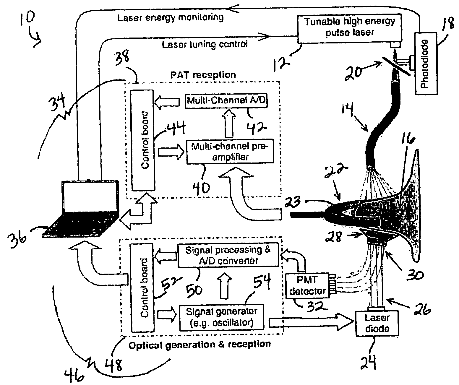
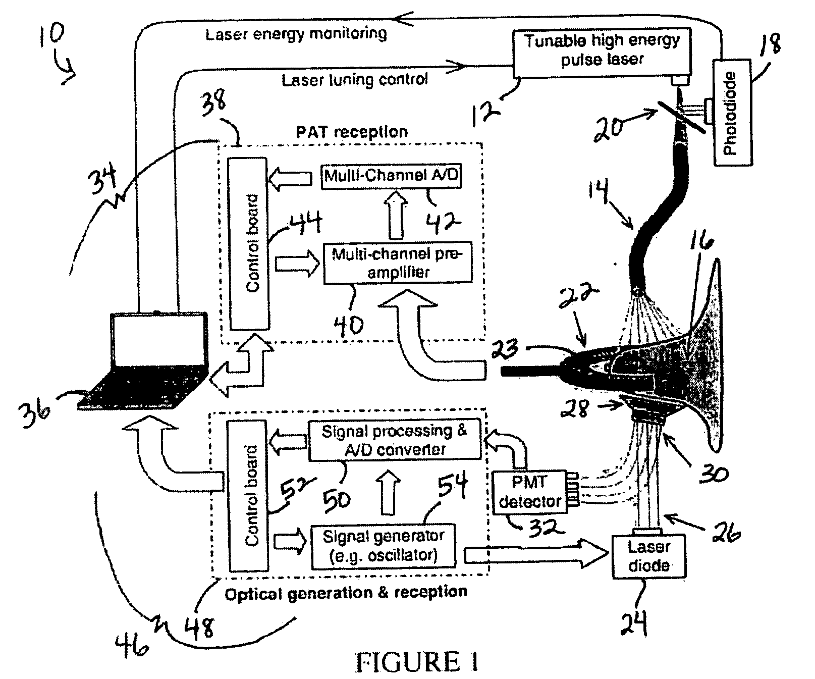
[0014]In accordance with the present invention, a photoacoustic guided diffuse optical imaging system and method for medical imaging, monitoring and diagnosis are provided which may employ both photoacoustic tomography (PAT) and diffuse optical imaging. The photoacoustic components in this system can provide morphological properties and optical information of subsurface biological tissues with hi...


PUM


Abstract

A system and method for photoacoustic guided diffuse optical imaging of a sample include at least one light source configured to deliver light to the sample, at least one ultrasonic transducer disposed adjacent to the sample for receiving photoacoustic signals generated due to optical absorption of the light by the sample, and at least one optical detector for receiving optical signals generated due to light scattered by the sample. A control system is provided in communication with the at least one light source, the ultrasonic transducer, and the optical detector for reconstructing photoacoustic images of the sample from the received photoacoustic signals and reconstructing optical images of the sample from the received optical signals. The priori anatomical information and spatially distributed optical parameters of biological tissues from the photoacoustic images employed in diffuse optical imaging may improve the accuracy of measurements and the reconstruction speed.

Description

CROSS-REFERENCE TO RELATED APPLICATIONS[0001]This application claims the benefit of U.S. provisional application Ser. No. 60 / 861,590 filed Nov. 29, 2006 which is incorporated by reference herein.BACKGROUND OF THE INVENTION[0002]1. Field of the Invention[0003]This invention relates to photoacoustic guided diffuse optical imaging.[0004]2. Background Art[0005]Photoacoustic tomography (PAT) may be employed for imaging tissue structures and functional changes, and describing the optical energy deposition in biological tissues with both high spatial resolution and high sensitivity. PAT employs optical signals to generate ultrasonic waves. In PAT, a short-pulsed electromagnetic source—such as a tunable pulsed laser source, pulsed radio frequency (RF) source or pulsed lamp—is used to irradiate a biological sample. The photoacoustic (ultrasonic) waves excited by thermoelastic expansion are then measured around the sample by high sensitive detection devices, such as ultrasonic transducer(s) m...

Claims


Application Information

Patent Timeline
IPC IPC(8): G01N21/47G01N21/59A61B5/00
CPCA61B5/0091A61B5/0095G01N21/4795G01N21/1702A61B5/4312
Inventor WANG, XUEDINGFOWLKES, BRIANCARSON, PAULCHAMBERLAND, DAVID
Owner RGT UNIV OF MICHIGAN
Learn More