
Ophthalmic ultrasound probe assembly

Inactive Publication Date: 2008-04-24
CAPISTRANO LABS
View PDF15 Cites 120 Cited by
  • Summary
  • Abstract
  • Description
  • Claims
  • Application Information

AI Technical Summary

Benefits of technology

[0010]The present invention specifically addresses and alleviates the above mentioned deficiencies associated with the prior art. More particularly, the present invention comprises an ultrasonic probe assembly that is uniquely adapted to provide accurate imaging of curved portions of the human anatomy such as the surface of the cornea by mechanically moving an ultrasonic transducer along an arcuate path that closely approximates the shape of the human eye. In this regard, the ultrasonic probe assembly of the present invention transmits an ultrasonic beam that is generally oriented substantially perpendicular to the surface of the cornea which minimizes oblique reflections of the ultrasonic beams so as to maximize reflected signal energy and accuracy.

Problems solved by technology

The fitting of the PIOL is a critical part of the surgical procedure as inserting a PIOL of incorrect size may result in rotational movement of the PIOL inside the eye which could cause damage to the natural lens upon which the PIOL rests.
Other serious complications could arise as a result of an incorrectly-sized PIOL.
For example, an incorrectly-fitted PIOL may result in blocking of the natural flow of fluid inside the eye which could eventually result in glaucoma.
The former results in reduction in echo strength and the latter results in slight geometric distortion.
Due to the curved outer surface of the eye, conventional “sectoring” or sector scanning ultrasonic probes are typically not suitable for ophthalmological purposes as such ultrasonic probes cannot maintain normality of the ultrasonic beam with the surface of the eye.

Method used


Image

  • Ophthalmic ultrasound probe assembly
  • Ophthalmic ultrasound probe assembly
  • Ophthalmic ultrasound probe assembly

Examples


Embodiment Construction

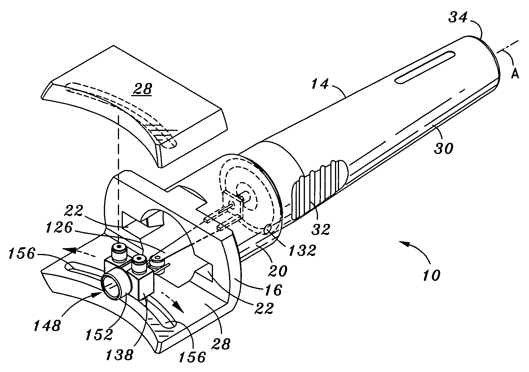
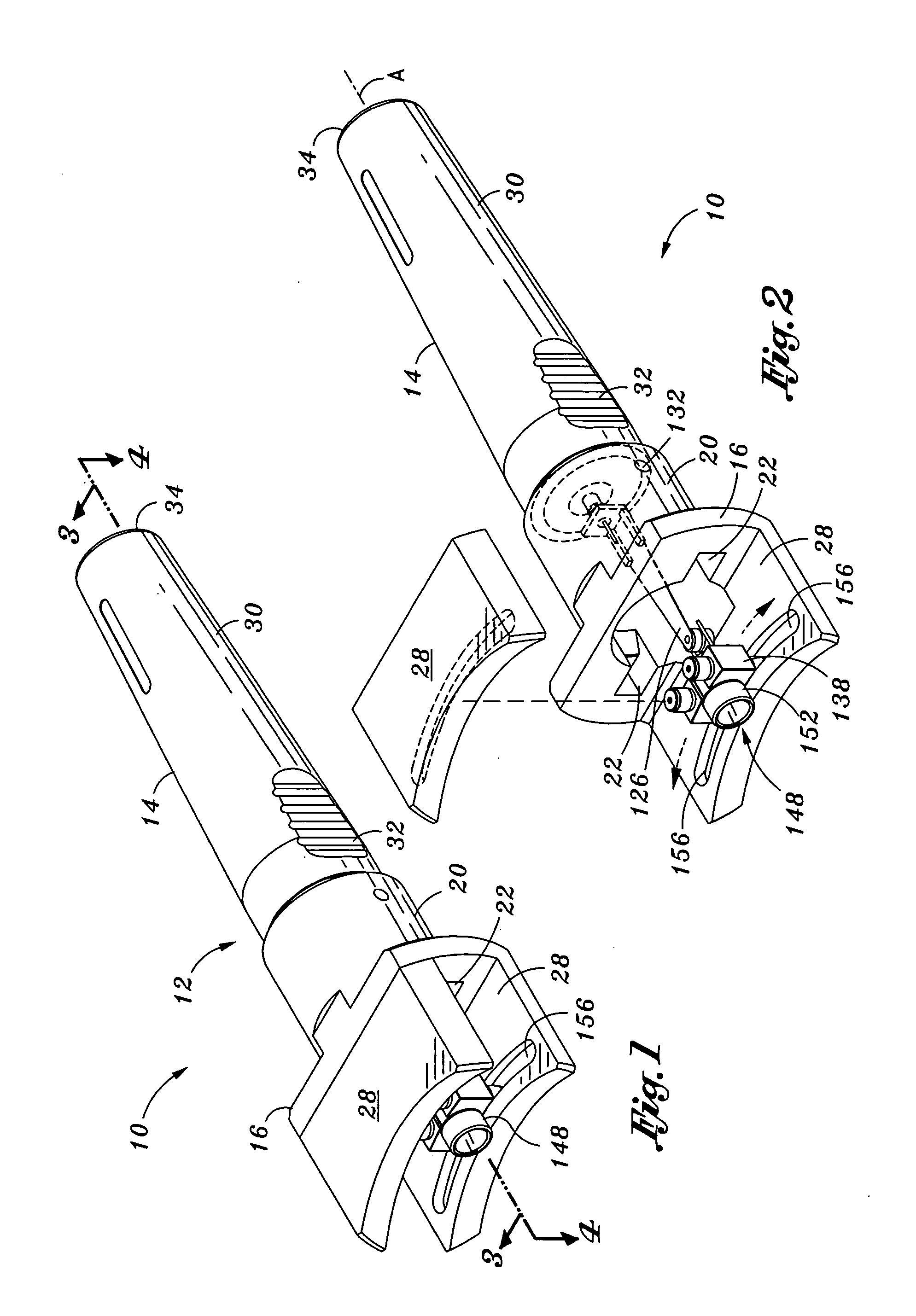
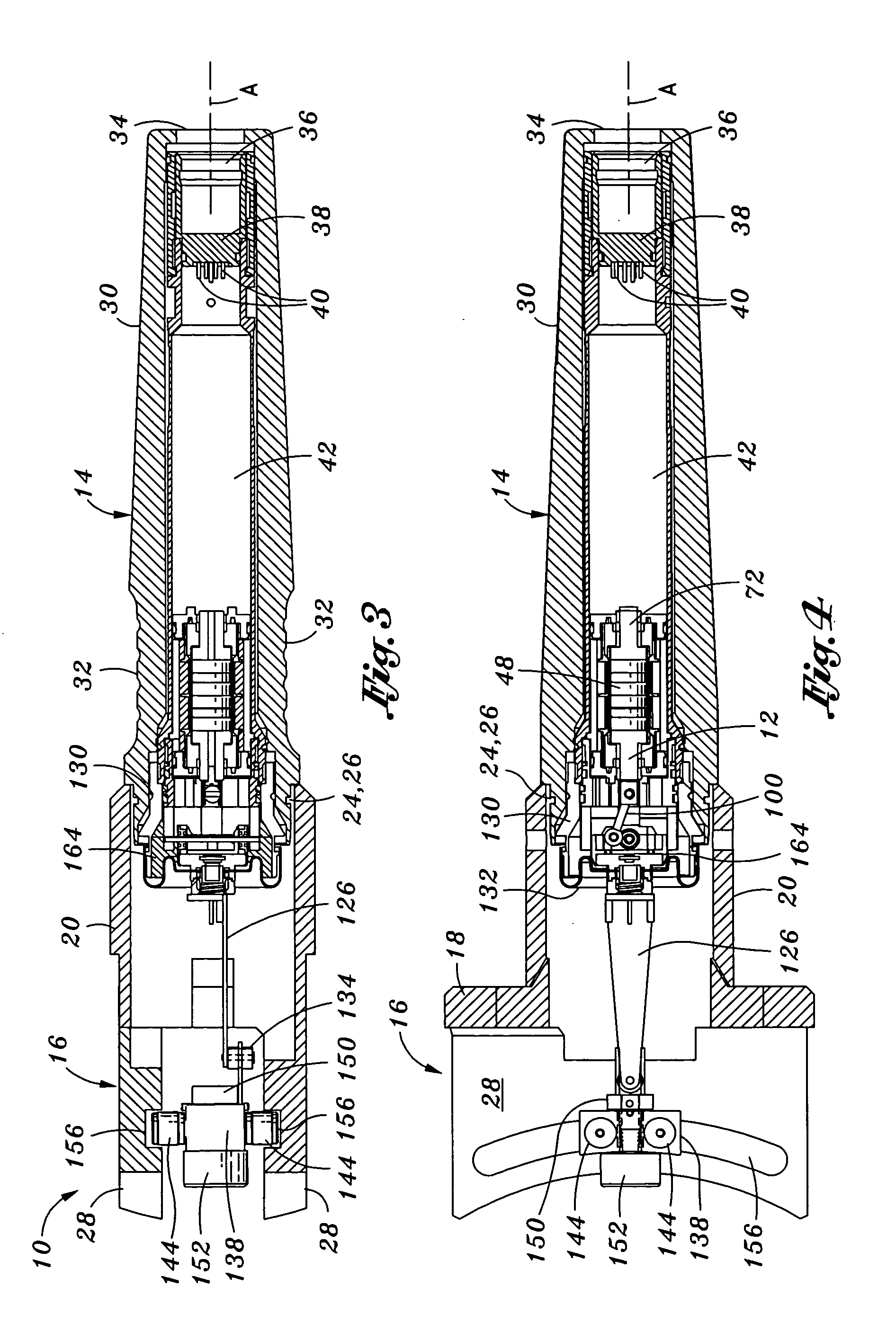
[0037]Referring now to the drawings wherein the showings are for purposes of illustrating preferred embodiments of the present invention only and not for purposes of limiting the same, FIGS. 1-18 illustrate an ultrasonic probe assembly 10 that is uniquely configured for ultrasonic imaging of convexly shaped anatomical structures such as the surface of the cornea. As will become apparent in the following description, the ultrasonic probe assembly 10 is specifically adapted to transmit an ultrasonic beam by a transducer 148 moving along an arcuate path in such a manner that the ultrasonic beam is oriented generally perpendicularly relative to the anatomical structure that is being imaged.

[0038]The ultrasonic probe assembly 10 incorporates a linear motor assembly 48 which reciprocates along a longitudinal axis A of the ultrasonic probe assembly 10. A connecting rod 100 connects the linear motor assembly 48 to a swivel base 114 having an extension arm 126 extending outwardly therefrom. ...


PUM


Abstract

An ultrasonic probe assembly comprises a housing defining a longitudinal axis and having a linear motor assembly, a swivel base, and an extension arm disposed therewithin. An imaging transducer is mounted on a free end of the extension arm and is specifically adapted to be moved along an arcuate path as a result of mechanical interconnection of the swivel base to the linear motor assembly. The swivel base upon which the extension arm is mounted is configured to be pivotable about a pivot axis oriented transversely relative to the longitudinal axis such that reciprocative motion of the linear motor assembly is converted in swiveling motion of the swivel base and oscillating translation of the transducer along an arcuate path such that the transducer axis is oriented generally perpendicularly relative to an anatomical structure having a convexly shaped outer surface.

Description

CROSS-REFERENCE TO RELATED APPLICATIONS[0001](Not Applicable)STATEMENT RE: FEDERALLY SPONSORED RESEARCH / DEVELOPMENT[0002](Not Applicable)BACKGROUND[0003]The present invention relates generally to ultrasonic probes and, more particularly, to a uniquely configured ultrasonic probe assembly specifically adapted for diagnostic imaging of convexly shaped anatomical structures.[0004]In the field of ultrasonic diagnostics, acoustic images of anatomical structures are utilized in the diagnosis of various medical disorders and conditions. In producing such images, beams of acoustic or ultrasonic energy are transmitted from a transducer such as a piezoelectric transducer into the body tissue of a patient. Reflected acoustic energy or echoes received by the ultrasonic probe are processed into an image format that is suitable for display. In ophthalmological diagnostic ultrasonography, ultrasound pulses are directed from a transducer into a patient's eye for imaging the anterior and posterior s...

Claims


Application Information

Patent Timeline
IPC IPC(8): G01N29/00
CPCA61B8/10A61B8/4411A61B8/4461
Inventor MEYERS, PAUL F.CEVELLOS, JOSE
Owner CAPISTRANO LABS
Learn More