Pressure buffer, ink-jet head, and ink-jet recording apparatus

a pressure buffer and inkjet technology, applied in printing and other directions, can solve the problems of deterioration of image quality, increased number of components, and failure of discharge, so as to suppress the fluctuation of pressure of ink, reduce manufacturing costs, and improve the effect of quality

Active Publication Date: 2008-04-10
SII PRINTEK
View PDF9 Cites 6 Cited by
  • Summary
  • Abstract
  • Description
  • Claims
  • Application Information

AI Technical Summary

Benefits of technology

[0023]According to the present invention, in the pressure buffer in which the opening portion of the chamber is provided on the upper portion of the pressure buffer, the ink flow path is provided inside the pressure buffer. With this structure, the ink flow outlet can be provided in the lower portion of the pressure buffer without impairing the function of filling the pressure buffer with ink. Therefore, it is possible to directly connect the pressure buffer to the ink-jet head to each other without using the ink supply path such as the tube shown in FIG. 2. As a result, the manufacturing costs can be reduced, and a peripheral space can be effectively used when the ink-jet head and the pressure buffer are to be arranged to be closer to each other.
[0024]Further, in the partition wall in the vicinity of the ink flow outlet, there is provided pressure suppressing means which suppresses the fluctuation in pressure of ink, such as a penetrating opening portion or an air pocket. As a result, even when unnecessary vibration is applied to the ink-jet head, the pressure fluctuation generated in the ink flow path between the opening portion of the chamber and the ink-jet head can be effectively reduced or alleviated, and generation of the density unevenness is suppressed, thereby making it possible to drastically improve the image quality.

Problems solved by technology

The pressure fluctuation causes deterioration in image quality in the case of recording characters or images on a recording medium, and further causes a discharge failure.
As a result, there arise problems in that the number of components is increased, and manufacturing costs are increased.
As a result, there arises a problem in that a peripheral space cannot be effectively used.
Therefore, there arise problems in that the pressure fluctuation causes a meniscus 104 to be displaced in a positive or negative direction, and a volume of ink droplets to be discharged, or a discharge rate is modulated, which leads to density unevenness.

Method used


Image

  • Pressure buffer, ink-jet head, and ink-jet recording apparatus
  • Pressure buffer, ink-jet head, and ink-jet recording apparatus
  • Pressure buffer, ink-jet head, and ink-jet recording apparatus

Examples


first embodiment

[0042]A structure of a pressure buffer according to a first embodiment of the present invention will be described in detail.

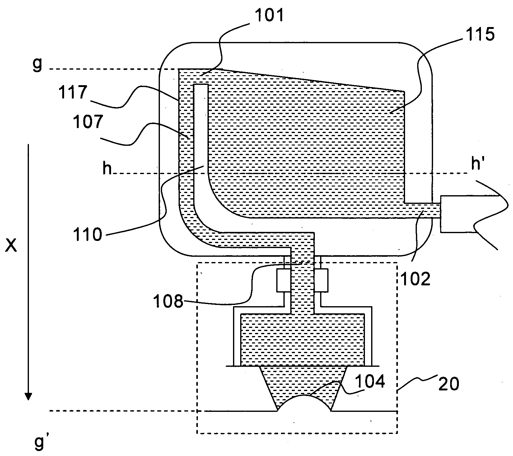
[0043]FIG. 4 is a diagram showing the structure of the pressure buffer according to the first embodiment of the present invention. FIG. 5 is a cross-sectional diagram of the pressure buffer of FIG. 4 taken along the line h-h′. An arrow X of FIG. 4 indicates a gravity direction. In other words, a lower side of FIG. 4 indicates a ground side.

[0044]As shown in FIG. 5, the pressure buffer has a concave portion 114 formed in at least one surface of a main body 112, and has a partition wall 110 in the vicinity of a side wall 117 of the concave portion 114. A flexible film 111 is applied to the concave portion 114 and to the partition wall 110 so as to hermetically seal the concave portion 114, thereby forming a chamber 115 and an ink flow path 107.

[0045]The pressure buffer of FIG. 4 has a lower portion in the gravity direction, and has an upper portion in a direction...

second embodiment

[0052]Next, a pressure buffer according to a second embodiment of the present invention will be described in detail.

[0053]FIG. 10 is a diagram showing a structure of the pressure buffer according to the second embodiment of the present invention. The arrow X of FIG. 10 indicates the gravity direction. In other words, the lower part of FIG. 10 indicates the ground side. In addition, the pressure buffer has a lower portion in the gravity direction, and has an upper portion in a direction opposite to the gravity direction. FIG. 11A is a diagram showing an example of directions in which vibration is applied to the ink-jet head, and specifically shows a vibration direction of each of an ink-jet head 2000 and a pressure buffer 2001. Arrows indicated by “+ ” and “−” of FIG. 10 each indicate the direction in which vibration is applied to the ink-jet head 2000 and the pressure buffer 2001. In this case, the arrows “+ ” and “−” each indicate the vibration in the vertical direction. FIG. 11B i...

third embodiment

[0063]In the second embodiment 2, as a method of alleviating the pressure fluctuation, there is illustrated a method in which the penetrating opening portion is provided in the partition wall, which partitions the link flow path from the chamber, so as to release the pressure fluctuation into the chamber. As long as the pressure fluctuation generated in the ink flowpath can be reduced or alleviated as described above, another method can be employed as the pressure suppressing means. For example, an air pocket for retaining the air may be formed by deforming a part of the partition wall provided in the vicinity of the ink flow outlet, and the pressure fluctuation may be absorbed by utilizing the resilience of the air.

[0064]A pressure buffer according to a third embodiment of the present invention which employs the above-mentioned method will be described below.

[0065]FIG. 14 is a diagram showing a structure of the pressure buffer according to the third embodiment.

[0066]In FIG. 14, an ...


PUM


Abstract

To reduce a fluctuation in pressure of ink supplied in an ink-jet head due to vibration of an ink tank through movement of a carriage, and to prevent density unevenness due to the pressure fluctuation from being caused in printing, the present invention provides a pressure buffer which is provided in an ink supply path connecting an ink-jet head to an ink supply portion for supplying ink to the ink-jet head, an opening portion is provided in a chamber of the pressure buffer, and the opening portion communicates with an ink flow path provided along a side wall of the chamber and is connected to an ink flow outlet provided in a position lower than the opening portion. In the ink flowpath in the vicinity of the ink flow outlet, a hole which communicates with the chamber is provided.

Description

BACKGROUND OF THE INVENTION[0001]1. Field of the Invention[0002]The present invention relates to an ink-jet head and an ink-jet recording apparatus for discharging ink onto a recording medium to be recorded thereon.[0003]2. Description of the Prior Art[0004]An ink-jet recording apparatus for recording characters and images on a recording medium by using an ink-jet head having a plurality of nozzles for discharging ink has been conventionally known.[0005]An outline of the ink-jet recording apparatus will be described below. FIG. 1 is a schematic diagram of the ink-jet recording apparatus which includes a pressure buffer. The ink-jet recording apparatus includes at least ink supply means 30 for supplying ink, an ink-jet head 20 for discharging ink, an ink supply path 50 which is a path for supplying ink from the ink supply means 30 to the ink-jet head 20, a pressure buffer 10 provided in the ink supply path 50 in the vicinity of the ink-jet head 20, and a carriage 40 which includes th...

Claims


Application Information

Patent Timeline
Patent Type & Authority Applications(United States)
IPC IPC(8): B41J2/17
CPCB41J2/17509B41J2/17556B41J2/17513
Inventor SAGA, YUKIHIROWATANABE, TOSHIAKI
Owner SII PRINTEK
Why Eureka
Try Eureka