
Inclined-hole drilling jig

a drilling jig and inclined-hole technology, which is applied in the field of drilling jigs, can solve the problems of increasing material and production costs, and often incurred deviations of the resulting holes, so as to facilitate the removal of drilling chips, enhance the structure, and introduce soundness and durability for the guide channel

Inactive Publication Date: 2008-03-27
LIN TUNG CHUAN
View PDF13 Cites 58 Cited by
  • Summary
  • Abstract
  • Description
  • Claims
  • Application Information

AI Technical Summary

Benefits of technology

The present invention is an inclined-hole drilling jig that improves upon conventional jigs by having multiple inclined guide channels. The guide seat has a concave chip groove to make drilling chip removal easier. The jig also contains a rigid liner tube to enhance its structure and make it more durable. These improvements make the jig more practical and useful for users.

Problems solved by technology

However, in a manual drilling operation, deviation of the resulting holes may be frequently incurred as illustrated in FIGS. 10a to 10d when wood veins are encountered, or when hands tremble.
Nevertheless, such inclined-hole drilling jig may still be imperfect for practical application.
Since there is only one inclined guide channel provided on the seat of the conventional inclined-hole drilling jig, the jig may fail to fit workpieces with various thicknesses and thus still cause an offset.
Although a supplemental guide seat with an alternative inclined guide channel can be implemented to solve this problem, the material and production costs are consequently increased; also, changing the seat during operation consequently causes inefficiency.

Method used


Image

  • Inclined-hole drilling jig
  • Inclined-hole drilling jig
  • Inclined-hole drilling jig

Examples


Embodiment Construction

[0025]Please refer to FIGS. 1 to 8 for preferred embodiments of the present invention. It is to be noted that the recited embodiments are for the purpose of illustration and are not intended to limit the present invention with the discussed structure.

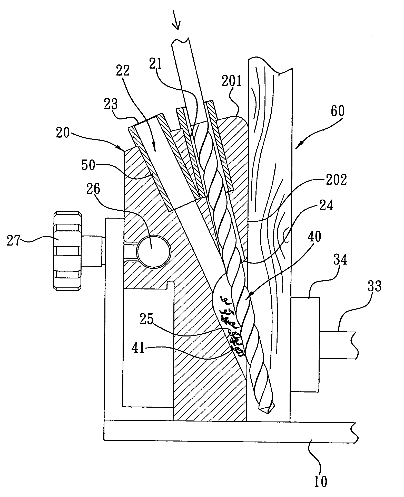
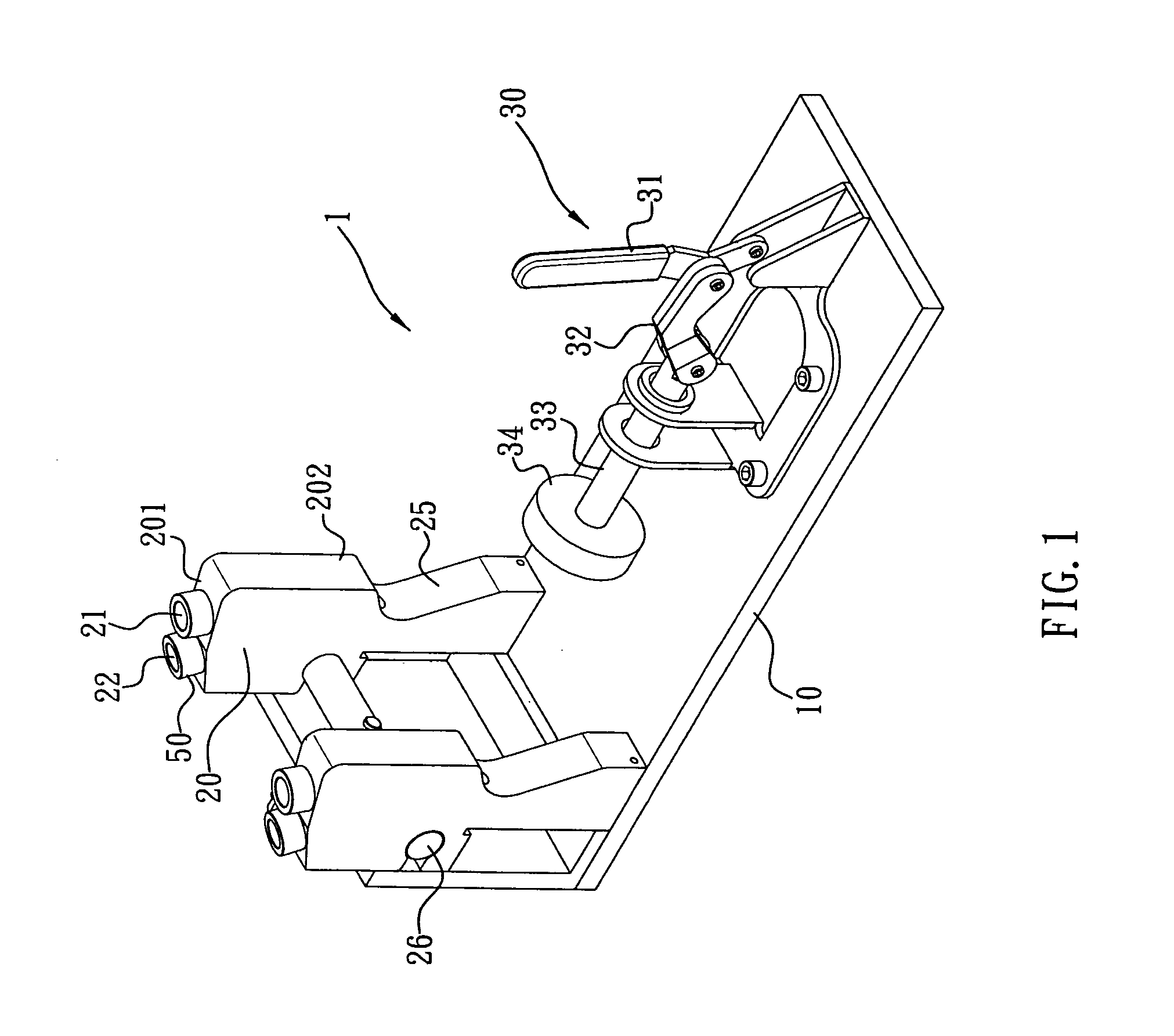
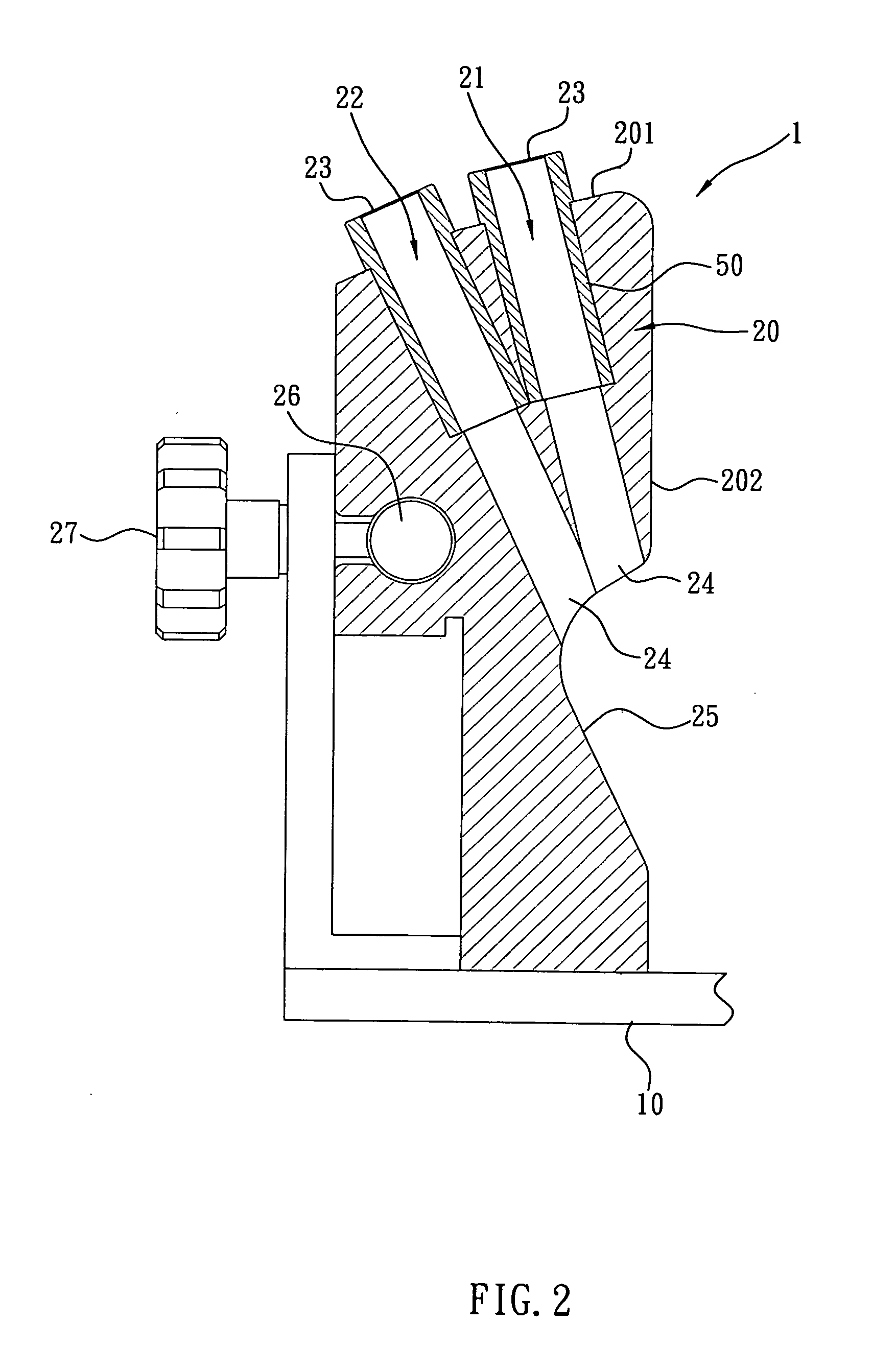
[0026]According to one embodiment of the present invention shown in FIG.1 and FIG. 2, the disclosed inclined-hole drilling jig primarily comprises a frame 10, at least one guide seat 20 (in the figures, shown as dual-channel guide seats) assembled thereon, and a workpiece positioner 30; wherein, the guide seats 20 each have plural inclined guide channels 21, 22 to accommodate and orient a drill 40 and the inlet ends 23 of the channels 21, 22 appear at the top surface 201 of the guide seat 20 while the outlet ends 24 thereof appear at one sidewall 202 of the guide seat 20. The present invention is characterized by at least one first inclined guide channel 21 and one second inclined guide channel 22 of the guide seats 20 with diverse incl...


PUM

PropertyMeasurementUnit
thicknessesaaaaaaaaaa
durabilityaaaaaaaaaa
thicknessaaaaaaaaaa

Abstract

An inclined-hole drilling jig primarily comprises a frame, at least one guide seat assembled thereon, and a workpiece positioner; wherein, the guide seats each have plural inclined guide channels to accommodate and orient a drill. The present invention is characterized by at least one first inclined guide channel and one second inclined guide channel of the guide seats with diverse inclinations, whereby, the guide seats can provide options for at least two diverse drilling inclinations to cater to users' various needs.

Description

BACKGROUND OF THE INVENTION[0001]1. Technical Field[0002]The present invention relates to drilling jigs and, more particularly, to an inclined-hole drilling jig having at least two inclined guide channels with diverse inclinations provided on the guide seat thereof.[0003]2. Description of Related Art[0004]There are some typical methods used to fix two wooden sticks perpendicular to each other; for instance, one involves nailing the sticks together, and another involves fastening them by some screw bolts. Before the latter method is to be practiced, plural holes with preset inclined routes must be drilled. However, in a manual drilling operation, deviation of the resulting holes may be frequently incurred as illustrated in FIGS. 10a to 10d when wood veins are encountered, or when hands tremble. Thus, some auxiliary apparatuses have been brought into the art to facilitate smooth and steady drilling operation; for example, an inclined-hole drilling jig.[0005]A conventional inclined-hol...

Claims


Application Information

Patent Timeline
Patent Type & Authority Applications(United States)
IPC IPC(8): B23B47/28
CPCB23B47/287Y10T408/567B23B2247/12B23B2247/10
Inventor LIN, TUNG-CHUAN
Owner LIN TUNG CHUAN
Learn More