Eureka AIR delivers breakthrough ideas for toughest innovation challenges, trusted by R&D personnel around the world.

Support Clamp For Retractor Bar Stock Of Generally Rectangular Cross-Section

a support clamp and bar stock technology, applied in the field of surgical tools, to achieve the effect of simple and intuitive tightening action

Inactive Publication Date: 2008-03-20
MINNESOTA SCI
View PDF55 Cites 32 Cited by
  • Summary
  • Abstract
  • Description
  • Claims
  • Application Information

AI Technical Summary

Benefits of technology

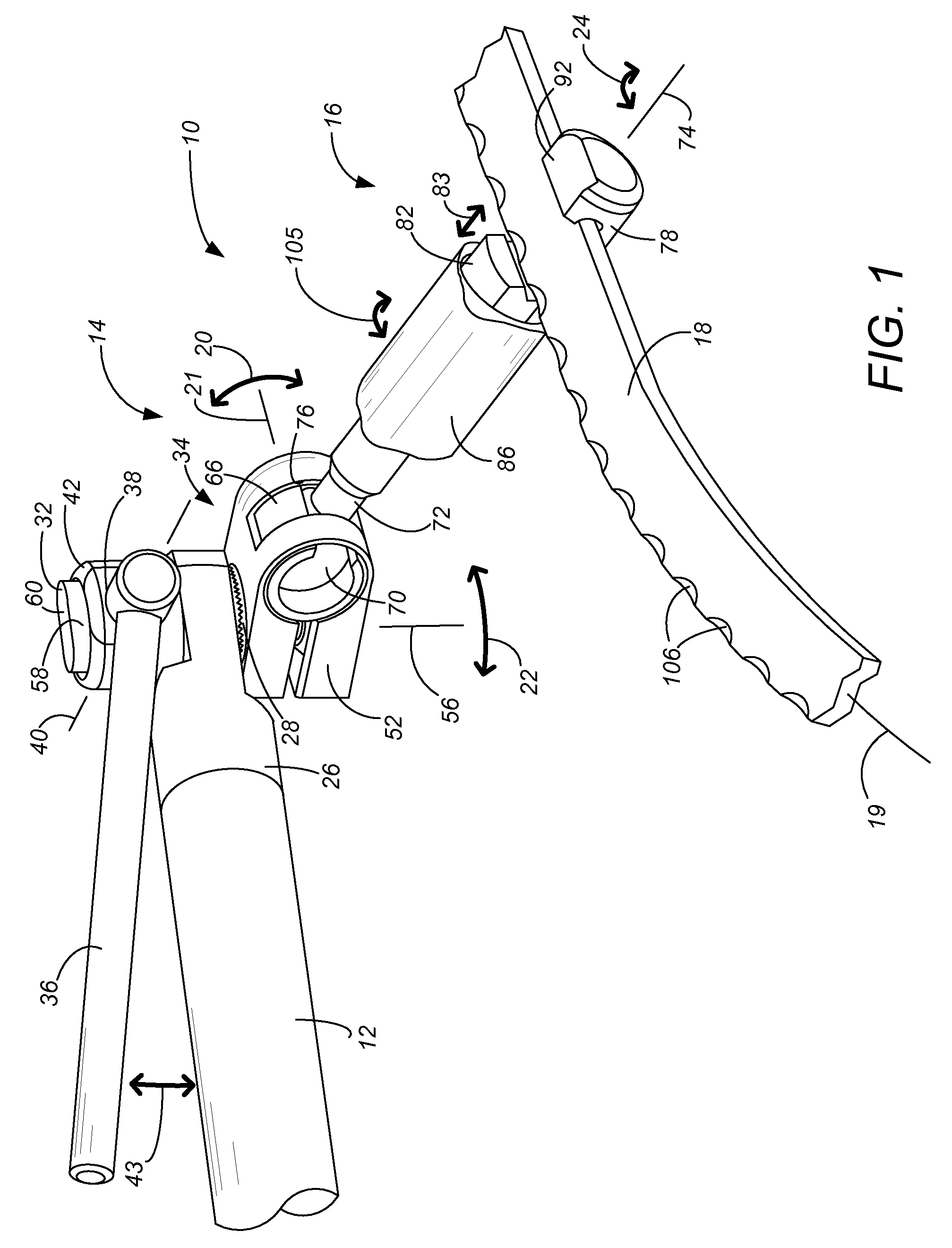
[0006]The present invention is a clamp for attachment of bar stock of generally rectangular cross-section, particular for use in surgical retractor systems, such as for attaching to a Bookwalter / Codman ring. The clamp has an inventive attachment mechanism that interacts with corners of the generally rectangular cross-section and permits clamping against a wide range of widths and thicknesses while still retaining a simple and intuitive tightening action. The clamp separately absorbs the clamping stress as a hoop stress, actuated with a mechanical advantage on the tightening control. In the preferred arrangement, the clamp makes a tripod top / planar bottom contact with the generally rectangular bar stock of the ring. An inventive articulating joint permits best fold up of the clamp, with a ball shaft which is constrained within the bisecting plane of the joint clamp.

Problems solved by technology

The outer side of the ring of the Bookwalter / Codman typically has regularly-spaced arc-shaped notches, but the notches do not prevent the Bookwalter / Codman ring from having a generally rectangular cross-section.

Method used


Image

  • Support Clamp For Retractor Bar Stock Of Generally Rectangular Cross-Section
  • Support Clamp For Retractor Bar Stock Of Generally Rectangular Cross-Section
  • Support Clamp For Retractor Bar Stock Of Generally Rectangular Cross-Section

Examples


Embodiment Construction

[0020]A first embodiment of a support clamp assembly 10 of the present invention is shown in FIGS. 1 and 2. The support clamp assembly 10 includes three basic components: an arm 12, an articulating joint 14, and a support clamp 16. The support clamp 16 attaches to the generally rectangular cross-section of the ring 18, a portion of which is shown in FIG. 1. The ring 18 may be any of the rings disclosed in U.S. Pat. Nos. 1,919,120, 1,963,173, 4,254,763, 4,421,108, 4,424,724, 4,434,791, 4,467,791, 5,375,481, 5,520,608, 5,520,610, 6,241,659, 6,530,882 and 6,808,493, all incorporated by reference. Each of these rings are generally provided by a bar having a longitudinal axis 19 and a generally rectangular cross-section transverse to the longitudinal axis.

[0021]As known in the art, the function of the arm 12 is to extend, most commonly horizontally, from a support post (not shown, typically mounted vertically on a bed frame) toward a surgical site location desired for the ring 18. The fu...


PUM


Abstract

A clamp is used to attach generally rectangular bar stock, such as existing Bookwalter / Codman rings, to a post in a surgical retractor system. The clamp interacts with corners of the ring at any of a wide range of widths and thicknesses, while still retaining a simple and intuitive tightening action such as through a rotational collar which absorbs some of the clamping force as a hoop stress. In the preferred arrangement, the clamp makes a tripod top / planar bottom contact with the generally rectangular bar stock of the ring. An articulating joint permits best fold up of the clamp, with a ball shaft which is constrained within the bisecting plane of the joint clamp. A spherical nut is used on the clamp bolt in one of the clamps, which permits some change in orientation of the clamp bolt when the clamp bolt is tightened using a cammed handle.

Description

CROSS-REFERENCE TO RELATED APPLICATION(S)[0001]This application claims priority from provisional application no. 60 / 845,580, filed Sep. 19, 2006, and also claims priority from provisional application no. 60 / 850,575, filed Oct. 10, 2006.BACKGROUND OF THE INVENTION[0002]The present invention relates to the field of surgical tools, and particularly to the design and manufacture of surgical retractor systems. Surgical retractor systems are used during surgery to bias and hold tissue in a desired position. As one example, some surgical procedures require anterior access to the spine, through the patient's abdomen. Tissue such as skin, muscle, fatty tissue and interior organs needs to be held retracted to the side so the surgeon can obtain better access to the vertebrae structures of primary interest.[0003]Such retractor assemblies may, for instance, include a frame element, commonly referred to as a “ring”, which is rigidly supported from the patient's bed above and around the surgical i...

Claims


Application Information

Patent Timeline
IPC IPC(8): A61B1/32
CPCA61B17/0206A61B17/02
Inventor BJORK, TODD M.BERG, CHRISTOPHER LEEJACOBSON, STEVEN KARL
Owner MINNESOTA SCI
Why Eureka
Eureka Blog
Learn More