
Three-dimensional display system

a display system and three-dimensional technology, applied in the field of visual display systems, can solve the problems of insufficient inspection, navigation, and comprehension of some types of multi-variate data, insufficient two-dimensional projection of 3d scenes, and high-quality images with excellent perspective depictions that are not met with widespread acceptan

Inactive Publication Date: 2008-03-20
APPLE INC
View PDF26 Cites 68 Cited by
  • Summary
  • Abstract
  • Description
  • Claims
  • Application Information

AI Technical Summary

Problems solved by technology

There is also a growing appreciation that two-dimensional projections of 3D scenes, traditionally referred to as “3D computer graphics”, can be insufficient for inspection, navigation, and comprehension of some types of multivariate data.
Without the benefit of 3D rendering, even high quality images that have excellent perspective depictions still appear unrealistic and flat.
However, most voyages into virtual reality are currently solitary and encumbered ones: users often wear helmets, special glasses, or other devices that present the 3D world only to each of them individually.
While these approaches have been generally successful, they have not met with widespread acceptance because observers generally do not like to wear equipment over their eyes.
In addition, such approaches are impractical, and essentially unworkable, for projecting a 3D image to one or more casual passersby, to a group of collaborators, or to an entire audience such as when individuated projections are desired.
Even when identical projections are presented, such situations have required different and relatively underdeveloped technologies, such as conventional autostereoscopic displays.
Displays of each type have been used in commercial display systems, and each has inherent strengths and weaknesses.
As a result, a typical volumetric display does not create a true 3D light field because the volume elements that are aligned depth-wise are not perceived to block one another.
However, the parallax barrier method typically requires the observer to remain stationary in one location.
Solutions to these problems have been long sought but prior developments have not taught or suggested any solutions and, thus, solutions to these problems have long eluded those skilled in the art.

Method used


Image

  • Three-dimensional display system
  • Three-dimensional display system
  • Three-dimensional display system

Examples


Embodiment Construction

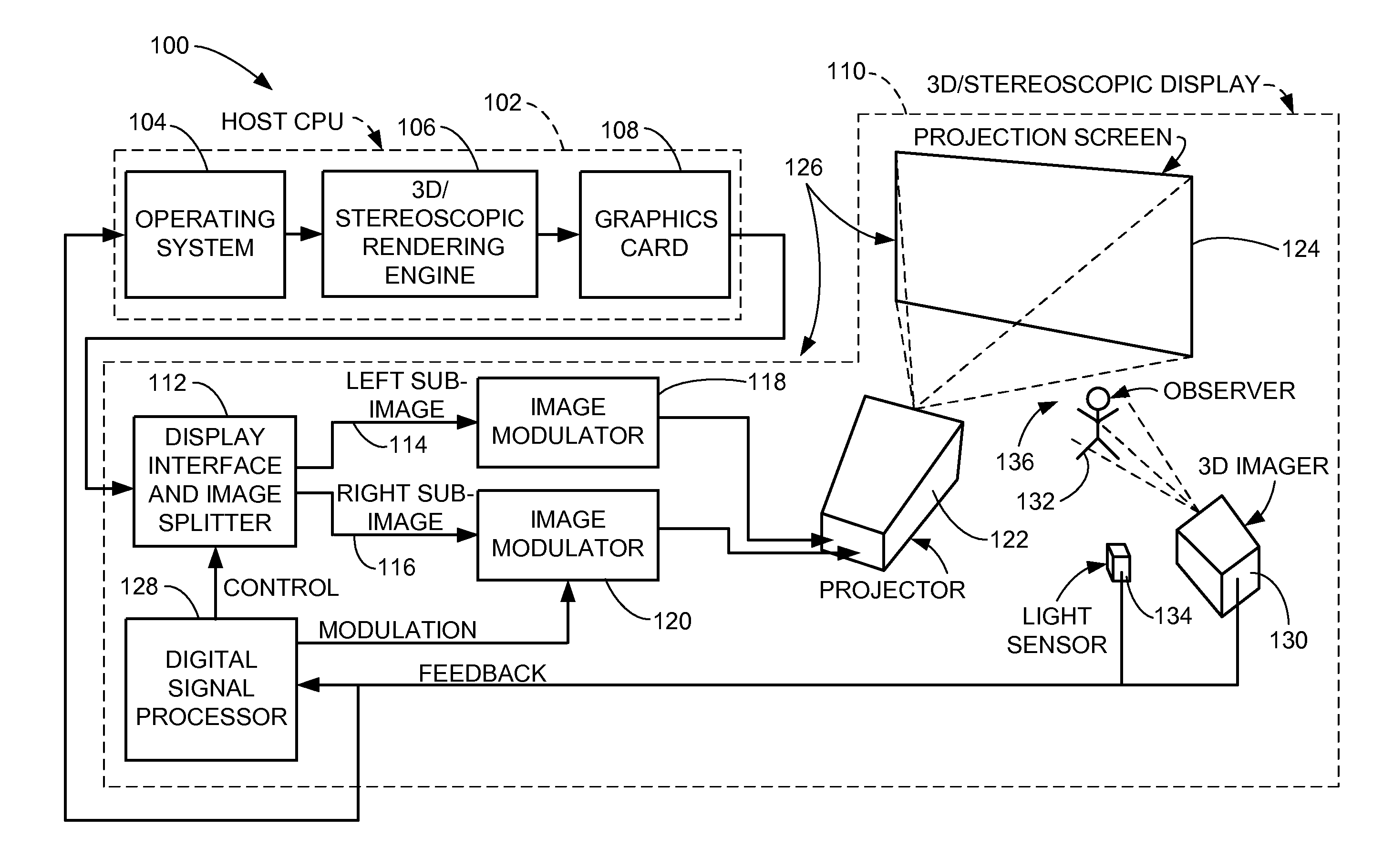
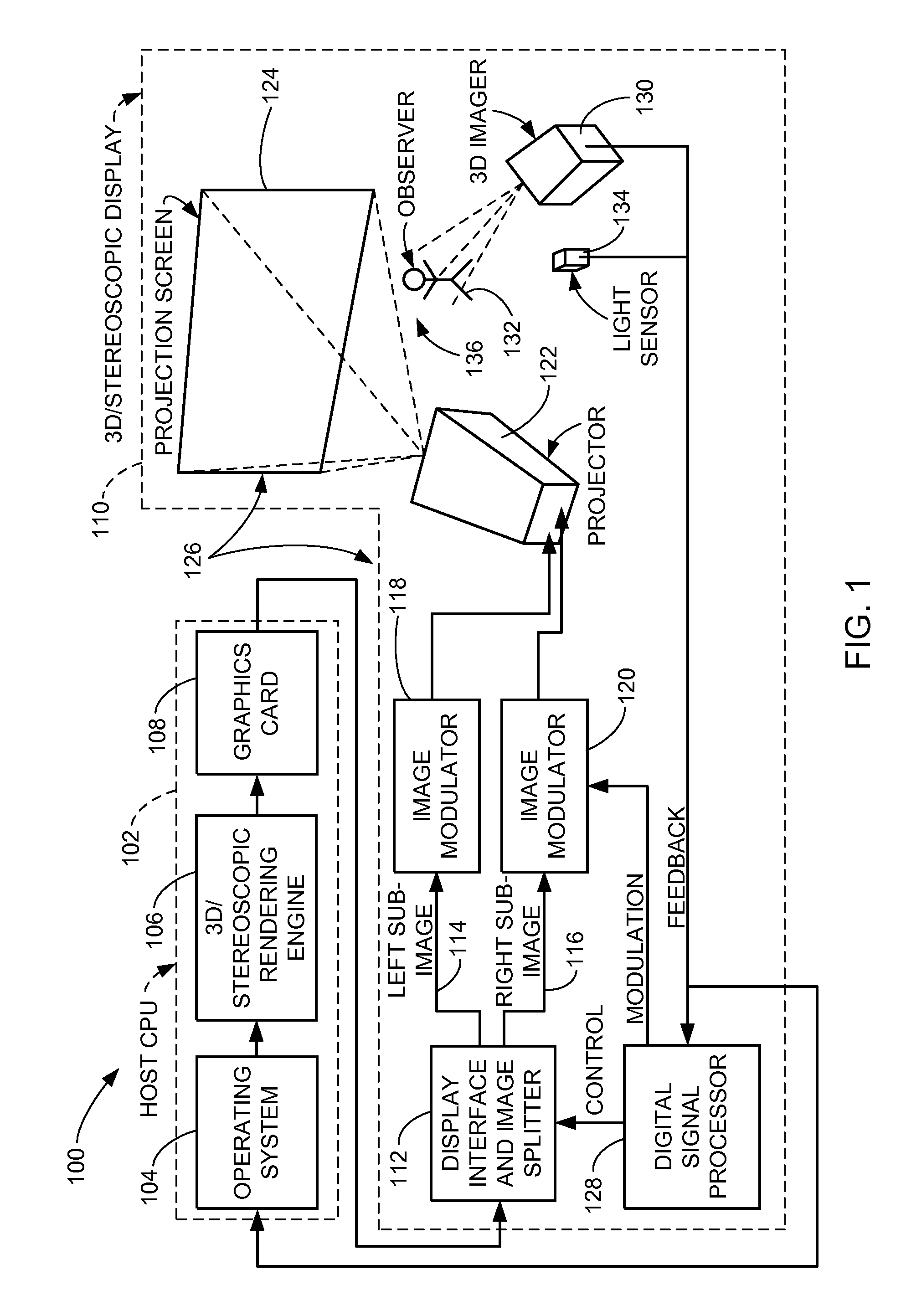
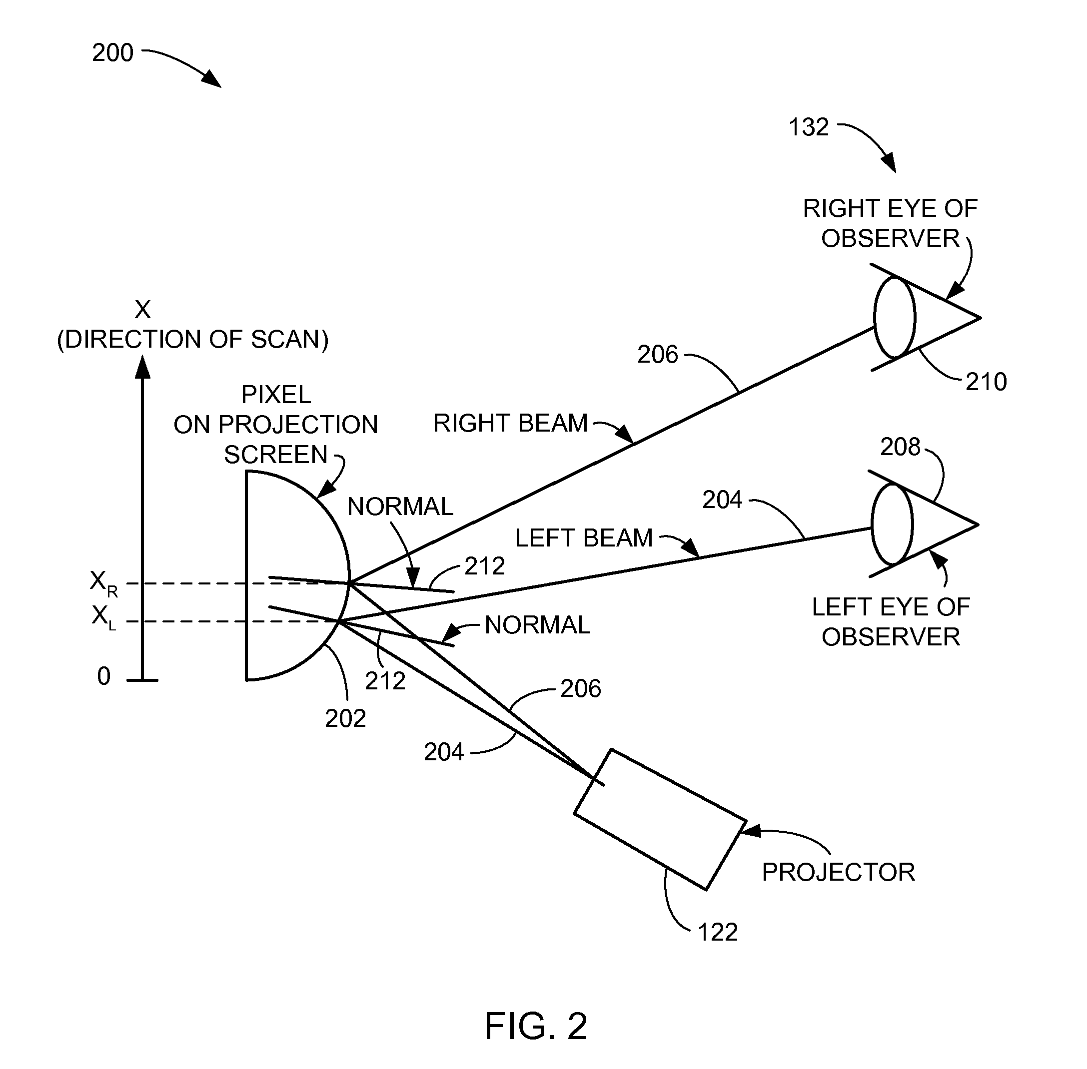
[0036]The following embodiments are described in sufficient detail to enable those skilled in the art to make and use the invention. It is to be understood that other embodiments would be evident based on the present disclosure, and that system, process, or mechanical changes may be made without departing from the scope of the present invention.

[0037]In the following description, numerous specific details are given to provide a thorough understanding of the invention. However, it will be apparent that the invention may be practiced without these specific details. In order to avoid obscuring the present invention, some well-known circuits, system configurations, and operational steps are not disclosed in detail.

[0038]Likewise, the drawings showing embodiments of the system are semi-diagrammatic and not to scale and, particularly, some of the dimensions are for the clarity of presentation and are shown greatly exaggerated in the drawing FIGs. Similarly, although the views in the drawi...


PUM


Abstract

A three-dimensional display system provides a projection screen having a predetermined angularly-responsive reflective surface function. Three-dimensional images are respectively modulated in coordination with the predetermined angularly-responsive reflective surface function to define a programmable mirror with a programmable deflection angle.

Description

CROSS-REFERENCE TO RELATED APPLICATION[0001]The present application contains subject matter related to a co-pending U.S. patent application Ser. No. 11 / 255,348, filed Oct. 21, 2005, entitled “THREE-DIMENSIONAL IMAGING AND DISPLAY SYSTEM”. This patent application is assigned to Apple Computer, Inc. and is identified by docket number P3830US1.TECHNICAL FIELD[0002]The present invention relates generally to visual display systems, and more particularly to a three-dimensional display system.BACKGROUND ART[0003]Modern three-dimensional (“3D”) display technologies are increasingly popular and practical not only in computer graphics, but in other diverse environments and technologies as well. Growing examples include medical diagnostics, flight simulation, air traffic control, battlefield simulation, weather diagnostics, entertainment, advertising, education, animation, virtual reality, robotics, biomechanical studies, scientific visualization, and so forth.[0004]The increasing interest and...

Claims


Application Information

Patent Timeline
IPC IPC(8): G06T15/00H04N13/363
CPCH04N13/0402H04N13/047H04N13/0459H04N13/363H04N13/302H04N13/368H04N13/00
Inventor KRAH, CHRISTOPH H.
Owner APPLE INC
Learn More