
Method and apparatus for displaying at least one video signal on at least one display

a technology of video signal and display device, applied in the field of video signals, can solve the problems of not being flexible, requiring a lot of space, and not being able to achieve the goal

Inactive Publication Date: 2008-03-13
VILLENEUVE CLAUDE +1
View PDF9 Cites 9 Cited by
  • Summary
  • Abstract
  • Description
  • Claims
  • Application Information

AI Technical Summary

Benefits of technology

[0007]According to a first aspect of the invention, there is provided a method for displaying at least one video signal on at least one display, the method comprising selecting at least one video signal to be displayed on the at least one display, providing, for each of the at least one selected video signal, at least one respective final display resolution and at least one respective target position on the at least one display, in at least one input unit, receiving a corresponding one of the selected at least one video signal, pre-scaling each of the corresponding one of the selected at least one video signal according to at least one respective intermediate display resolution compatible with said at least one respective final display resolution, in at least one output unit, post-scaling at least one pre-scaled video signal to obtain at least one post-scaled video signal at said at least one respective final display resolution, the selecting and pre-scaling enabling optimization of a bandwidth between the at least one input unit and the at least one output unit and displaying the at least one post-scaled video signal each at its the at least one respective target position on the at least one display.
[0008]According to another aspect of the invention, there is provided an apparatus for displaying at least one video signal on at least one display, the apparatus comprising a video signal selecting unit for selecting at least one video signal to be displayed on the at least one display for receiving, for each of the at least one video signal, at least one respective final display resolution and at least one respective target position on the at least one display, at least one input unit, each for receiving a corresponding one of the at least one video signal, each of the at least one input unit comprising a corresponding pre-scaling unit for pre-scaling each of the corresponding one of the at least one video signal according to at least one respective intermediate display resolution compatible with the at least one respective display resolution, at least one output unit, each for receiving a corresponding one of the at least one pre-scaled video signal, each of the at least one output unit comprising a corresponding post-scaling unit for post-scaling the corresponding one of the at least one pre-scaled video signal to obtain corresponding post-scaled video signals at the at least one respective final display resolution, each of the at least one output unit for providing the corresponding post-scaled video signals each at its at least one respective target position on a corresponding one of the at least one display, wherein the selecting in the video signal selecting unit and the pre-scaling in each of the at least one input unit enables an optimization of bandwidth between the at least one input unit and the at least one output unit.

Problems solved by technology

Unfortunately achieving this objective is very cumbersome, especially when large amount of video signals are involved.
Unfortunately, due to the bandwidth required by each video signals, the hardware required to display a large amount of signals on a plurality of displays is often very important and requires a lot of space which is a drawback.
Moreover, such setting is not very flexible as the choice of having a given video signal on a given display is not easy to meet and may require many steps which lead to losses in productivity and competitiveness for operators.

Method used


Image

  • Method and apparatus for displaying at least one video signal on at least one display
  • Method and apparatus for displaying at least one video signal on at least one display
  • Method and apparatus for displaying at least one video signal on at least one display

Examples


Embodiment Construction

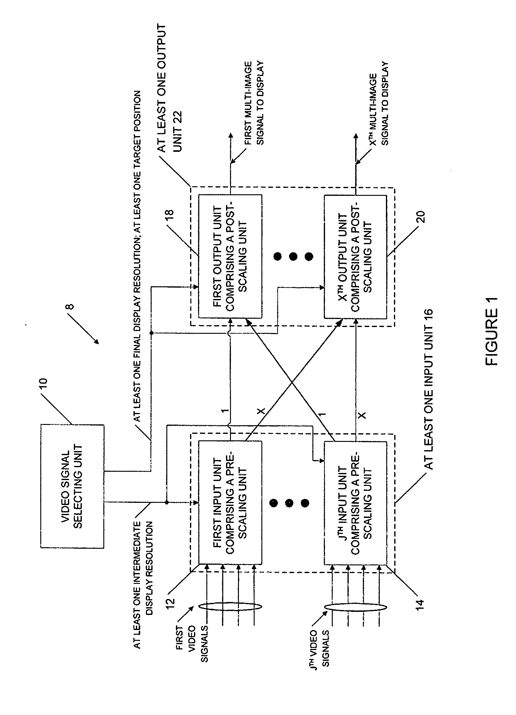
[0025]Now referring to FIG. 1, there is shown an embodiment of an apparatus for displaying at least one video signal on at least one display 8.

[0026]The apparatus 8 comprises a video signal selecting unit 10, at least one input unit comprising a pre-scaling unit 16 and at least one output unit comprising a post-scaling unit 22.

[0027]In the embodiment disclosed in FIG. 1, the at least one input unit comprising a pre-scaling unit 16 comprises a first input unit comprising a pre-scaling unit 12, . . . and a Jth input unit comprising a pre-scaling unit 14. Still in this embodiment, the at least one output unit comprising a post-scaling unit 22 comprises a first output unit comprising a post-scaling unit 18, . . . and a Xth output unit comprising a post-scaling unit 20.

[0028]The video signal selecting unit 10 is used to provide at least one intermediate display resolution, at least one final display resolution and at least one target position. More precisely, the at least one intermediat...


PUM


Abstract

According to a first aspect of the invention, there is provided a method for displaying at least one video signal on at least one display, the method comprising selecting at least one video signal to be displayed on the at least one display, providing, for each of the at least one selected video signal, at least one respective final display resolution and at least one respective target position on the at least one display, in at least one input unit, receiving a corresponding one of the selected at least one video signal, pre-scaling each of the corresponding one of the selected at least one video signal according to at least one respective intermediate display resolution compatible with said at least one respective final display resolution, in at least one output unit, post-scaling at least one pre-scaled video signal to obtain at least one post-scaled video signal at said at least one respective final display resolution, the selecting and pre-scaling enabling optimization of a bandwidth between the at least one input unit and the at least one output unit and displaying the at least one post-scaled video signal each at its the at least one respective target position on the at least one display.

Description

CROSS-REFERENCE TO RELATED APPLICATIONS[0001]This is the first application filed for the present invention.TECHNICAL FIELD[0002]This invention relates to the field of video signals. More precisely, this invention pertains to a method and apparatus for displaying at least one video signal on a at least one display.BACKGROUND OF THE INVENTION[0003]It is very desirable to output a plurality of video signals on a plurality of displays. Unfortunately achieving this objective is very cumbersome, especially when large amount of video signals are involved.[0004]Because the displays are now able to achieve great resolutions, a large plurality of video signals may be involved and required to be displayed.[0005]Unfortunately, due to the bandwidth required by each video signals, the hardware required to display a large amount of signals on a plurality of displays is often very important and requires a lot of space which is a drawback. Moreover, such setting is not very flexible as the choice of...

Claims


Application Information

Patent Timeline
Patent Type & Authority Applications(United States)
IPC IPC(8): H04N11/02
CPCG09G5/14G09G2340/0407H04N5/268G09G2340/125G09G2360/04G09G2340/0464
Inventor VILLENEUVE, CLAUDECHAGNON, ING. MARC
Owner VILLENEUVE CLAUDE
Learn More