
Reducing Common Mode Noise of Power Factor Correction Converters Using General Balance Concept

a power factor correction and general balance technology, applied in the direction of electric variable regulation, process and machine control, instruments, etc., can solve the problems of affecting the efficiency of the converter, and the use of the switching arrangement as a source of common mode (cm) noise, etc., to achieve the effect of substantial cancellation of common mode noise, low volume, and simple switching arrangemen

Inactive Publication Date: 2008-03-13
VIRGINIA TECH INTPROP INC
View PDF7 Cites 15 Cited by
  • Summary
  • Abstract
  • Description
  • Claims
  • Application Information

AI Technical Summary

Benefits of technology

[0008]It is therefore an object of the present invention to provide a technique for substantial cancellation of common mode noise which is simple, inexpensive and of low volume and capable of providing as high as a 40 db reduction of common mode (CM) noise and which is sufficient to allow simplification of EMI filtering and without requiring a performance penalty such as loss of efficiency.

Problems solved by technology

However, use of a switching arrangement is a source of common mode (CM) noise due to the unavoidable voltage variation dv / dt which results from the power switching function and the unavoidable parasitic capacitance between the power circuit and ground.
CM noise is thus very difficult to control particularly due to the parasitic capacitance between respective portions of the power circuit and the case, the circuit board, other circuits and the like, which are subject to unpredictable variation from slight changes in geometry and proximity to various structures.
Attempts to reduce CM noise have generally been attempted through strict symmetric design (which is not always compatible with requirements of the powered circuit and often requires additional components which may be unnecessary for any other reason) or through intensive filtering which also compromises efficiency and is often expensive and consumes significant space.
Even so, reduction in CM noise has generally been limited to about 20 db which is insufficient to allow simplification or reduction in size and weight of EMI filtering arrangements.

Method used


Image

  • Reducing Common Mode Noise of Power Factor Correction Converters Using General Balance Concept
  • Reducing Common Mode Noise of Power Factor Correction Converters Using General Balance Concept
  • Reducing Common Mode Noise of Power Factor Correction Converters Using General Balance Concept

Examples


Embodiment Construction

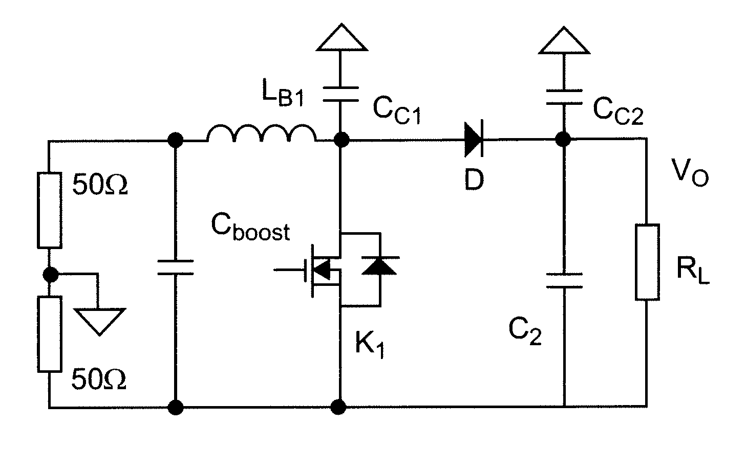
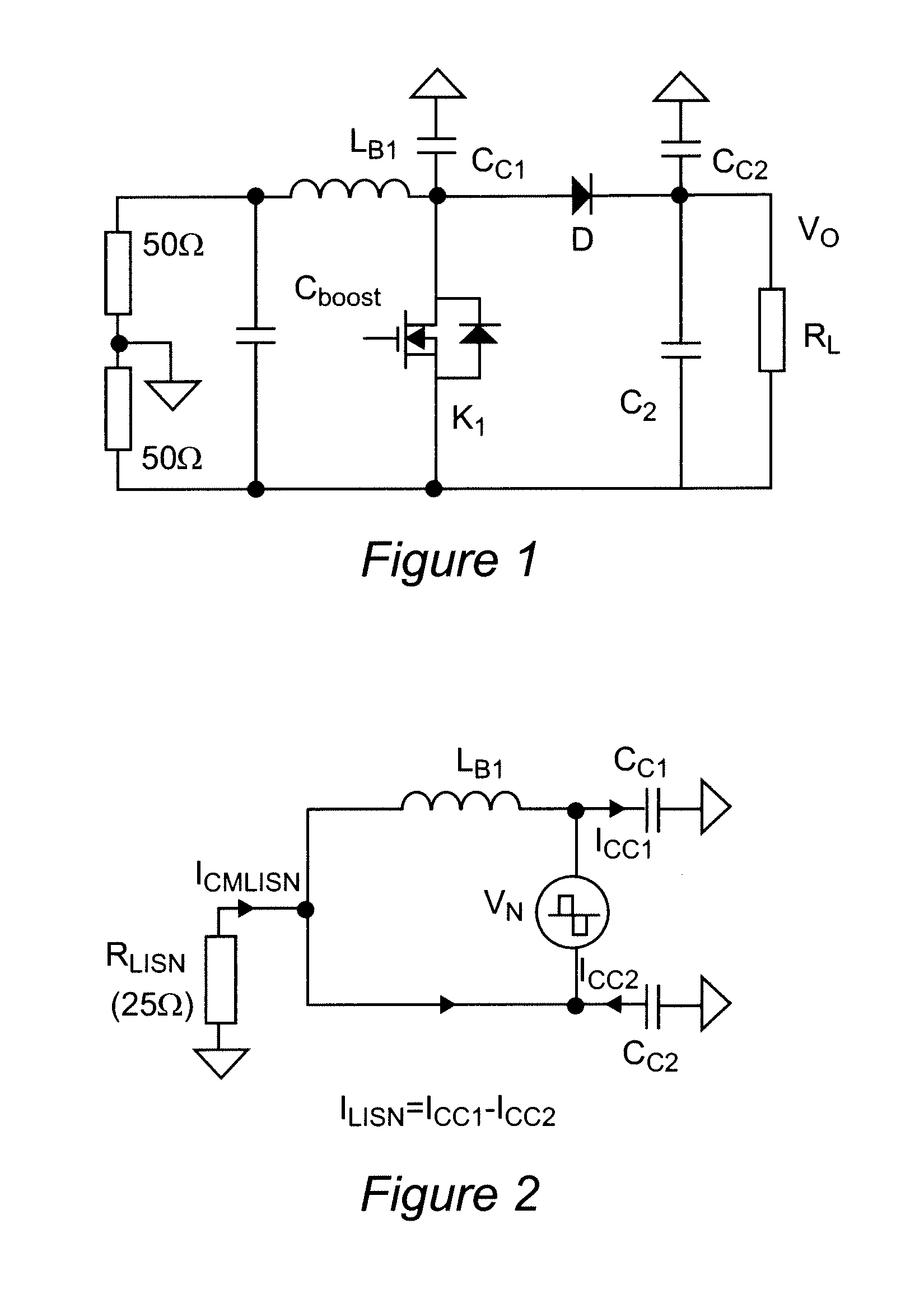
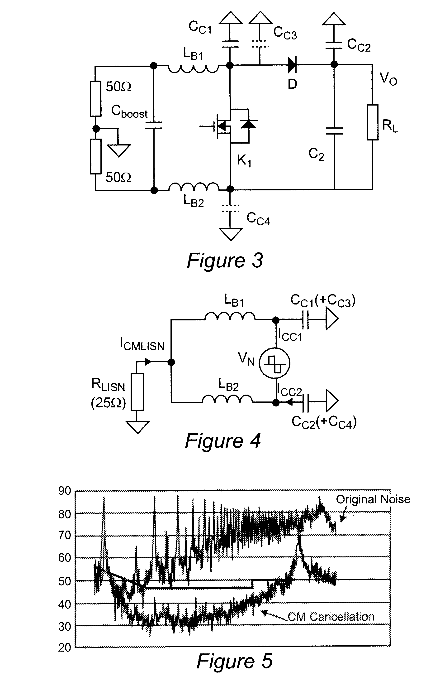
[0017]Referring now to the drawings, and more particularly to FIG. 1, there is shown a schematic circuit diagram of a boost power factor correction converter (but without an input rectifier, bridge or other power input arrangement being illustrated since the nature of the power input is irrelevant to an understanding of the invention and principles thereof sufficient to its practice) of a general type to which the invention is particularly applicable. The voltage boost circuit of FIG. 1 will also enable the application of the principles of the invention to other types of power supplies and converters such as DC to DC converters, dual boost PFC converters and inverters, forward converters, flyback converters or any other power circuit topologies. Further, it should be understood that since FIG. 1 and the equivalent circuit model of FIG. 2 are arranged to facilitate an understanding of the basic principles of common mode (CM) noise and its causes, no portion of either Figure is admitt...


PUM


Abstract

Common mode (CM) noise is substantially canceled in a switching power supply circuit such as a boost converter by providing a split inductor and analyzing the switching power supply circuit as a bridge circuit formed of the switch, portions of the split inductor and parasitic capacitances of respective portions of the power supply circuit. The bridge can then be balanced by addition of capacitance in parallel with the parasitic capacitance of a respective portion of the power supply circuit or dividing the split inductor such that a ratio of inductances of respective portions of the split inductor approximates a ratio of parasitic capacitances of the respective power supply circuit portions which may be measured or otherwise empirically determined. CM noise reduction of up to 40 db can be achieved without symmetric circuit design, addition of circuit elements or complex filtering having added cost, space requirements and power losses. Further, such a reduction in common mode noise allows simple EMI filtering arrangements to be employed further reducing cost and space requirements for the power supply circuit.

Description

STATEMENT OF GOVERNMENT INTEREST[0001]This invention was made in connection with National Science Foundation Contract EEC-9731677. The U. S. Government may have certain rights in this invention.BACKGROUND OF THE INVENTION [0002]1. Field of the Invention[0003]The present invention generally relates to power supplies and power factor correction power converters and, more particularly to reduction of common mode (CM) noise produced therein.[0004]2. Description of the Prior Art[0005]Most electronic devices currently in use operate on a more or less constant voltage direct current (DC) power rather than alternating current (AC) generally used for power distribution. This voltage is generally produced by a power supply or power converter included in such electronic devices which may include an AC to DC power supply such as a rectifier and filter and a further regulator stage to stabilize the output voltage at a desired value. It is also common, if not required, to provide an arrangement f...

Claims


Application Information

Patent Timeline
Patent Type & Authority Applications(United States)
IPC IPC(8): G05F1/00
CPCH02M1/4225H02M1/44Y02B70/126H02M2001/0064H02M3/156Y02B70/10Y02P80/10H02M1/0064
Inventor WANG, SHUOLEE, FREDKONG, PENGJU
Owner VIRGINIA TECH INTPROP INC
Learn More