Locking bone plate

a bone plate and locking technology, applied in bone drill guides, medical science, surgery, etc., can solve the problems of reducing surgical flexibility, increasing complexity of procedures, and requiring more operating room time, and achieve the effect of greater flexibility of choi

Inactive Publication Date: 2008-03-06
SWISS ORTHOPEDIC SOLUTIONS SA
View PDF17 Cites 28 Cited by
  • Summary
  • Abstract
  • Description
  • Claims
  • Application Information

AI Technical Summary

Benefits of technology

[0019] An object of the invention is to provide an orthopaedic surgeon greater flexibility of choice in that a threaded peg providing secure fixing can be positioned at any interval along the bone plate, including at its extreme ends.

Problems solved by technology

Although an improvement over the inserts noted above, the locking positions are pre-defined, and only available in limited locations, which also reduce surgical flexibility.
This is not desirable because this requires more operating room time and adds complexity to the procedure.
This limits the choice of placement during surgery if the need arises.
Friction locks are not reliable and come lose more easily than threaded locked holes.
The result of such a design is inferior to that of the threaded plate and screw designs discussed below.
However, when such a bone plate is fixed to a bone, these discontinuous recesses are exposed and may potentially come into contact with and potentially aggravate muscle tissue.
Nevertheless, there are often trauma situations that are best served by the threaded portion being at the extreme ends of the bone plate and / or at various positions throughout the plate.
In addition, sometimes there is no specific center of the fracture—in such a situation, use of the combi-hole design is limited.
Therefore, the final configuration upon fixing is indeterminate and, due to the small amount of contact between the threads of the insert or screw and the slot, as well as tile fact that the screw will be able to slide in one direction, the design does not appear to lend itself to reliable fixing.

Method used


Image

  • Locking bone plate
  • Locking bone plate
  • Locking bone plate

Examples


Embodiment Construction

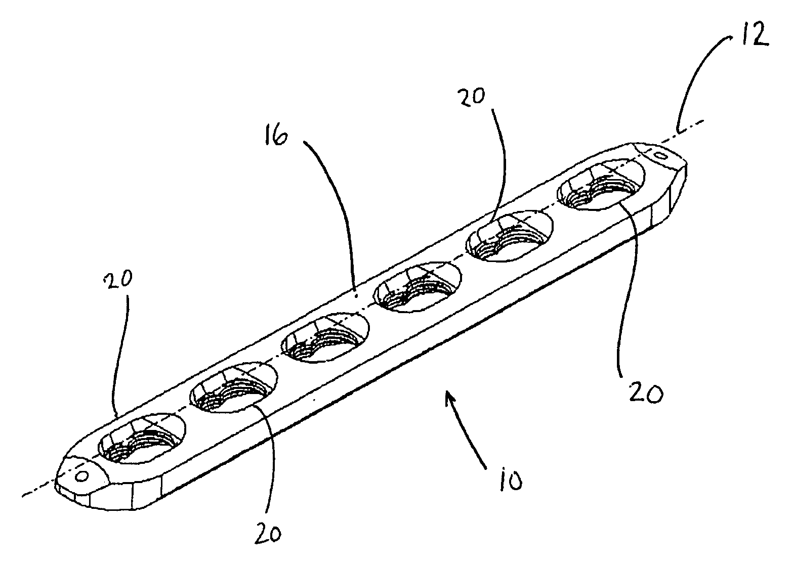
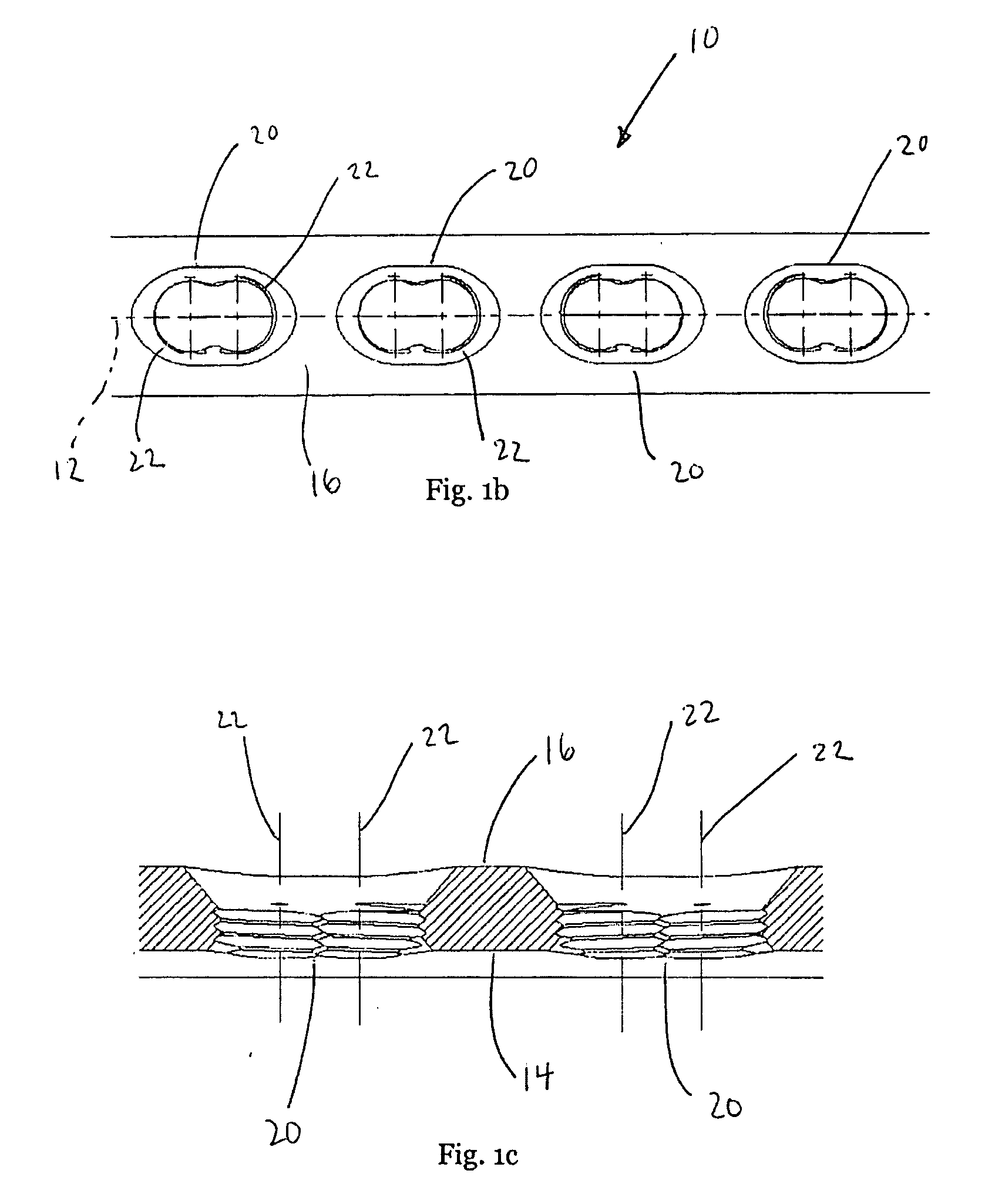
[0042] Referring now to FIGS. 1a to 1d, a bone plate 10 with a longitudinal axis 12 has a bone-contacting bottom side 14 and a top side 16. Multiple sets 20 of overlapping holes 22 communicate through the plate 10 from the top side 16 to the bottom side 14. The overlapping holes 22 are adapted to receive a bone screw 24 with a head 26 having a thread 30 and, on an opposite end 32, a body having a bone-engaging thread 34 (shown in FIG. 8).

[0043] The multiple sets 20 of overlapping holes 22 allow for further adjustability and flexibility in positioning of the bone plate 10 during surgery. The overlapping holes 22 are formed normal to the top side 16 of the plate 10 (shown in FIGS. 1c and 1d).

[0044] Referring now to FIG. 2a and 2b, the overlapping holes 22 have multifaceted surfaces 36. In one embodiment, the multifaceted surface 36 is a threaded surface 10 (shown in FIG. 2a). In another embodiment, the multi-faceted surface 36 is a coaxial series of annular grooves 42 (shown in FIG....


PUM


Abstract

A bone plate with a longitudinal axis has a bone-contacting bottom side and a top side. Sets of overlapping holes communicate through the plate from the top to the bottom side. The overlapping holes have multifaceted surfaces such as a threaded surface or a coaxial series of annular grooves. The sets of overlapping holes are adapted to receive a bone screw with a head and a bone-engaging thread.

Description

CROSS REFERENCE TO RELATED APPLICATIONS [0001] This application is a continuation application of U.S. patent application Ser. No. 10 / 551,295 of the same name, filed Sep. 24, 2005, the content of which is incorporated herein by reference thereto.BACKGROUND OF THE INVENTION [0002] This invention relates to devices, implants and prostheses used in orthopedic surgery, and, more particularly, to bone plates used to reinforce fractured bones and thus promote healing. [0003] A compressive screw system, also known as the DCS system, is a bone plate system that has been used in trauma surgery for many years. The procedures for use of this system are well documented by the AO Institute, an institute having as one of its goals, the promotion of new orthopaedic surgical procedures. This system included a bone plate having slots communicating therethrough. A land in which the slot is wider at one end defines a stepped surface adjacent the portion of the slot that extends through the bone plate. ...

Claims


Application Information

Patent Timeline
Patent Type & Authority Applications(United States)
IPC IPC(8): A61B17/58A61B17/56A61B17/17A61B17/80A61B19/02
CPCA61B17/1728A61B17/8052A61B17/8057A61B50/30A61B17/80A61B17/58
Inventor YOUNG, ROBERT
Owner SWISS ORTHOPEDIC SOLUTIONS SA
Why Eureka
Try Eureka