
Remote cinematography viewing device

a cinematography and viewing device technology, applied in the field of remote video monitoring and control system, can solve the problems of poor ergonomics of known devices, insufficient durability of connecting and housing components for cinematography applications, and small display, and achieve the effect of sufficient size and resolution

Inactive Publication Date: 2008-03-06
CARLSON ROBERT C
View PDF16 Cites 10 Cited by
  • Summary
  • Abstract
  • Description
  • Claims
  • Application Information

AI Technical Summary

Benefits of technology

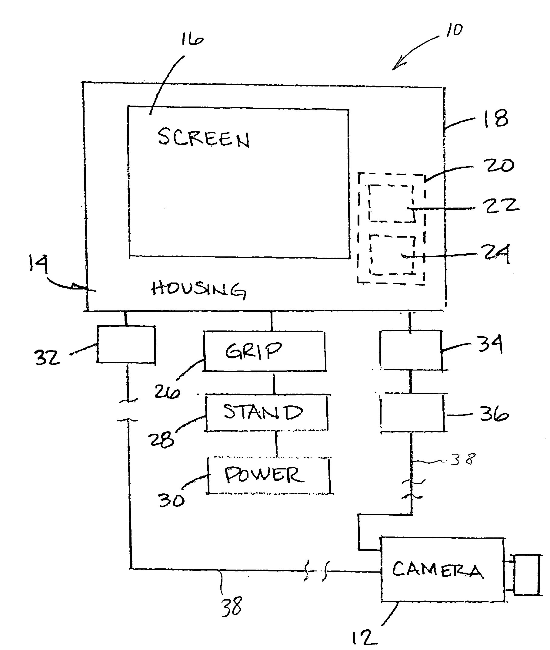
[0019]In accordance with the principles of the present invention, a remote video monitoring and control system for use in cinematography includes an ergonometrically balanced display device of sufficient size and resolution to display images useful in cinematography. A handgrip is secured to the display device, and a power source is secured to the base. A stand provides stability, and permits the system to be freestanding. A video signal receiving mechanism is operatively connected to the display device, and receives video signals from a remote camera. A camera control arrangement is operatively connected to the display device to generate camera control signals from an operator of the camera control arrangement. A camera control signal transmitting mechanism transmits camera control signals from the camera control arrangement to the remote camera.

Problems solved by technology

These connectors and housing components have proven to lack sufficient durability for use in cinematography applications, and are routinely destroyed by being dropped or knocked over.
Further, known devices have poor ergonomics, most notably small displays and awkward power source configurations.
These monitors are too small to display images useful in cinematography.
The combination of small display, awkward handles, and poor battery placement make known devices difficult to use and expensive to fabricate.
Although these known video systems provide some advantages, they present significant drawbacks as well.
Many known remote video systems are intended for security systems and the like, and are unsuitable for cinematography.
Other systems have poor ergonomics and lack durability.

Method used


Image

  • Remote cinematography viewing device
  • Remote cinematography viewing device
  • Remote cinematography viewing device

Examples


Embodiment Construction

[0024]While this invention is susceptible of embodiment in many different forms, there is shown in the drawings, and will herein be described in detail, exemplary embodiments, with the understanding that the present disclosure is to be considered as illustrative of the principles of the invention and not intended to limit the invention to the exemplary embodiments shown and described.

[0025]FIG. 1 illustrates a remote video monitoring and control system 10 in accordance with the principles of the present invention. The remote video monitoring and control system 10 is adapted and constructed for use in cinematography using a remote camera 12 capable of transmitting video signals and receiving control signals. The ergonometrically balanced system 10 includes a display device 14 capable of displaying video images from the remote camera 12. The display device 14 includes a display screen 16 of sufficient size and resolution to display images useful in cinematography. It is contemplated t...


PUM


Abstract

A remote video monitoring and control system for use in cinematography includes an ergonometrically balanced display device of sufficient size and resolution to display images useful in cinematography. A handgrip base is secured to the display device, and a power source is secured to the base. A video signal receiving mechanism is operatively connected to the display device, and receives video signals from a remote camera. A camera control arrangement is operatively connected to the display device to generate camera control signals from an operator of the camera control arrangement. A camera control signal transmitting mechanism transmits camera control signals from the camera control arrangement to the remote camera.

Description

CROSS-REFERENCE TO RELATED APPLICATIONS:[0001]NoneSTATEMENT AS TO RIGHTS TO INVENTIONS MADE UNDER FEDERALLY-SPONSORED RESEARCH AND DEVELOPMENT:[0002]None[0003]1. Field of the Invention[0004]The invention relates generally to remote viewing devices, and specifically to arrangements for remote, real-time viewing and controlling of cinematography.[0005]2. Description of Related Art[0006]Video equipment has long been used in various ways in the cinematographic process. One common application is “video assist”, wherein a low-resolution (typically single-chip) video camera (color or b &w) is used to pick up an image in the view finding system of a movie camera. Video images captured by the camera are sent to a monitor, where they can be recorded for playback. Such images are seldom used for editing, but for monitoring aspects of the shot, such as framing. It is common for camera assistants to have a small onboard LCD monitor showing them the video tap image to assist in camera operation....

Claims


Application Information

Patent Timeline
IPC IPC(8): H04N5/222
CPCH04N7/18
Inventor CARLSON, ROBERT C.
Owner CARLSON ROBERT C
Learn More