
Retractable Tow Rope Apparatus

a tow rope and apparatus technology, applied in the field of tow ropes, can solve the problems of not providing a convenient means for transporting a tow rope from a storage location, devices that do not enable a user to easily transport and mount a length of tow rope, etc., and achieve the effect of easy mounting to or removal from a boa

Inactive Publication Date: 2008-03-06
CZAJKOWSKI MARGARET R
View PDF13 Cites 18 Cited by
  • Summary
  • Abstract
  • Description
  • Claims
  • Application Information

AI Technical Summary

Benefits of technology

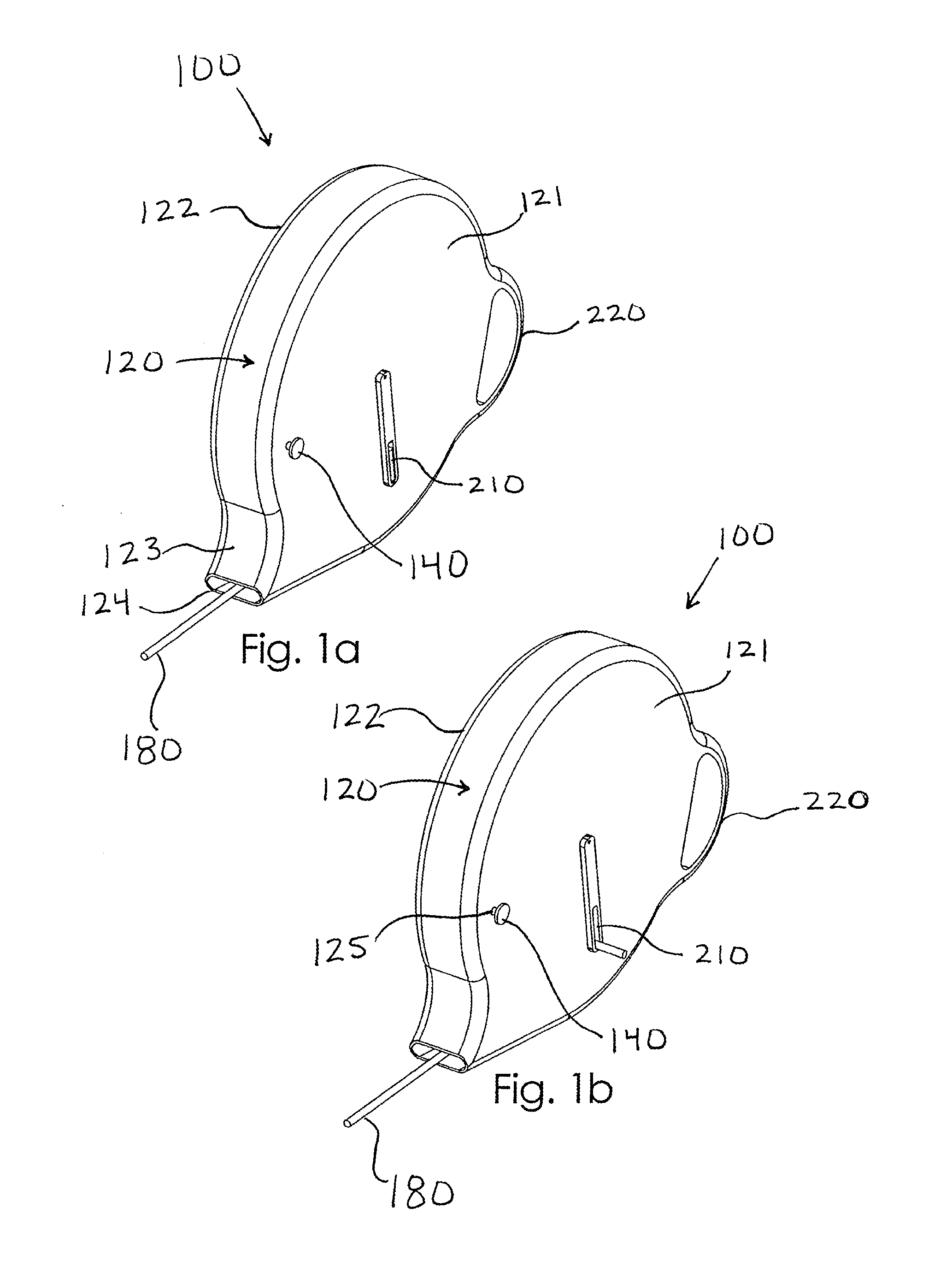
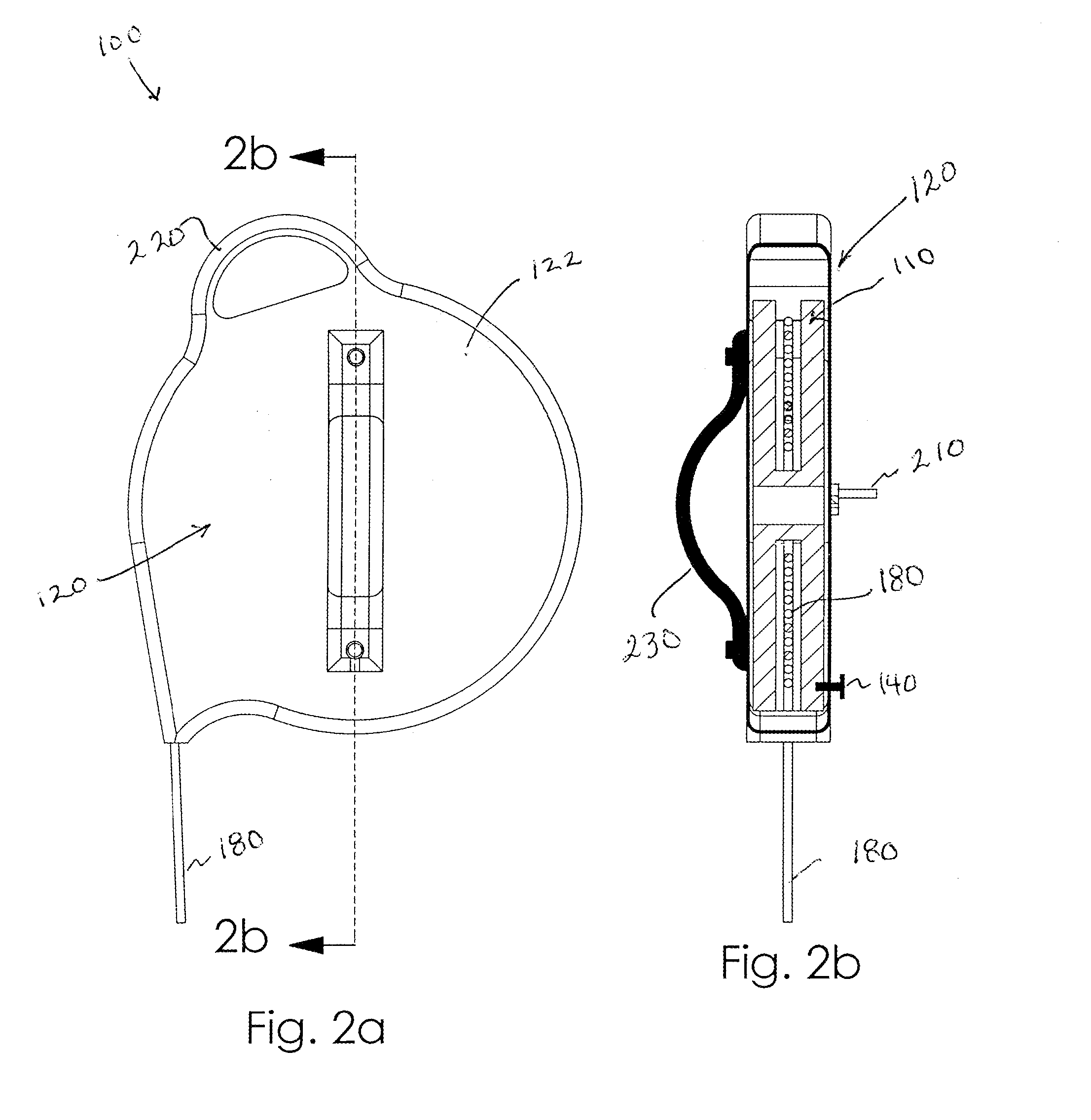
[0006]The casing includes a handle by which the entire retractable tow rope apparatus may transported by a user. Means for releasably mounting the device to the boat during use is also provided. A movable fairlead may also be mounted to the casing adjacent the aperture through which a tow rope enters the casing for evenly positioning a tow rope on the spool during retraction. A squeegee may also be positioned proximate the aperture for squeezing water from the tow rope during retraction.
[0009]Still another object of this invention is to provide a retractable tow rope apparatus, as aforesaid, in which the automatic retraction may be conveniently stopped by a user, if desired.
[0012]A still further object of this invention is to provide a retractable tow rope apparatus, as aforesaid, that may be easily mounted to or removed from a boat.

Problems solved by technology

Although presumably effective for their intended purposes, the existing devices do not provide a convenient means for transporting a tow rope from a storage location to a boat and back, for mounting the rope to the boat for use, or for easily gathering the rope following use.
Specifically, the existing devices do not enable a user to easily transport and mount a length of tow rope, retract the rope automatically without electrical power, have means for selectively stopping the retraction, enable excess water to escape from the housing during retraction, or have means for squeezing water from the rope itself during retraction.

Method used


Image

  • Retractable Tow Rope Apparatus
  • Retractable Tow Rope Apparatus
  • Retractable Tow Rope Apparatus

Examples


Embodiment Construction

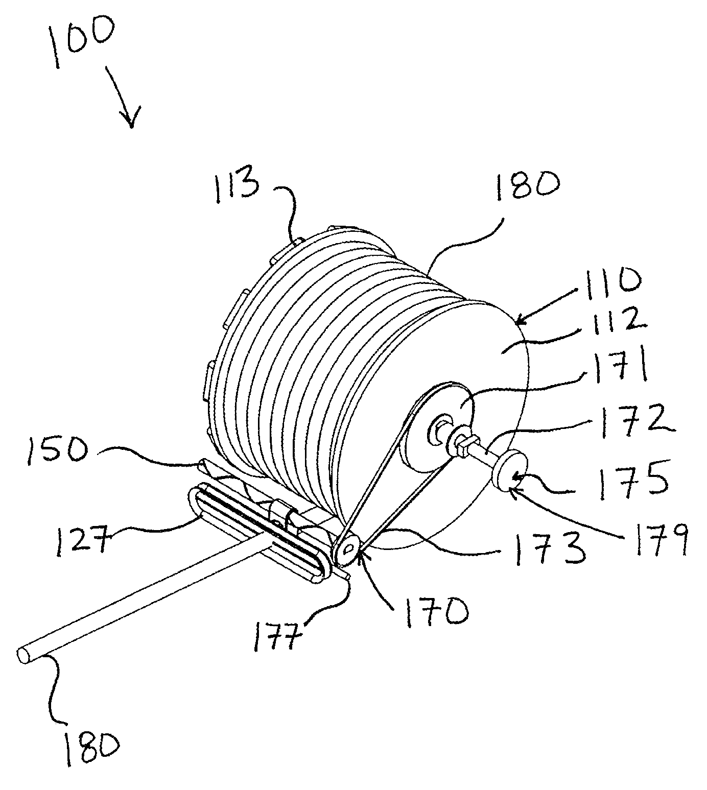
[0026]A retractable tow rope apparatus 100 particularly for use with watersports and / or with a boat according to the present invention will now be described in detail with reference to FIGS. 1a through 7c of the accompanying drawings. More particularly, a retractable tow rope apparatus 100 according to the current invention may include an internal spool 110, an outer casing 120, a retraction spring 130, a spool brake 140, a drive screw 150, a moving fairlead 160, a drive assembly 170, and a rope 180.

[0027]The internal spool 110 (also referred to herein as a “hollow spool”) has opposed first and second ends 111, 112, and a first flange 113 may extend outwardly from the first end 111 as shown in FIGS. 4 and 5. The first end 111 and / or the first flange 113 may define a plurality of indentations 114 (also referred to herein as “grooves”) which may or may not extend through the first end 111. Though not shown in the drawings, the spool 110 may be understood to define an imaginary center ...


PUM


Abstract

A retractable tow rope apparatus according to the present invention includes a hollow spool mounted for rotational movement inside a casing. A retraction spring is positioned inside the spool and is coupled to the spool and to the casing for selectively moving the spool therein. One end of the spool includes a flange defining a plurality of grooves. A spool brake is mounted to the casing for selective engagement with a respective groove, whereby to selectively stop the spool from paying out or retracting the tow rope. A retractable handle is mounted to the casing and coupled to the spool, enabling a user to manually turn the spool. The casing includes a handle for carrying the device. A bracket may be attached to the casing for releasably mounting the device to a boat.

Description

BACKGROUND OF THE INVENTION[0001]This invention relates generally to tow ropes and related storage devices and, more particularly, to a retractable tow rope apparatus for storing and mobilizing a water ski rope.[0002]A long length of rope is utilized when pulling a water skier behind a motorized boat. At the conclusion of a skier's time of skiing, such as when he falls down or a different skier desires to take a turn, the rope may be partially pulled back into the boat. Certainly, the rope must be pulled back within the boat when the overall skiing outing is completed for the day. The rope must then be allowed to dry and is stored away until its next use.[0003]Various devices for reeling or retracting a rope or cable have been proposed in the prior art. Although presumably effective for their intended purposes, the existing devices do not provide a convenient means for transporting a tow rope from a storage location to a boat and back, for mounting the rope to the boat for use, or f...

Claims


Application Information

Patent Timeline
Patent Type & Authority Applications(United States)
IPC IPC(8): B65H75/42
CPCB63B35/815B65H75/40B65H75/4402B65H75/4471B65H75/4431B65H75/446B65H2701/35B65H75/4407B63B34/60
Inventor CZAJKOWSKI, MARGARET R.
Owner CZAJKOWSKI MARGARET R
Learn More