
Hybrid Micro/Macro Plate Valve

a micro-macro plate valve and micro-macro plate technology, which is applied in the direction of valve details, valve arrangement, valve operating means/release devices, etc., can solve the problems of solenoid-assisted cv and limit the packaging options of the cooling system in which they are installed

Inactive Publication Date: 2008-02-21
MICROSTAQ
View PDF99 Cites 17 Cited by
  • Summary
  • Abstract
  • Description
  • Claims
  • Application Information

AI Technical Summary

Benefits of technology

[0015]Alternatively, a microvalve for controlling the operation of another valve is disclosed. The microvalve includes a plurality of layers defining a body where the body has a chamber and a plurality of ports in fluid communication with the chamber. A movable portion is positioned within the chamber, the movable portion being selectively moved to one of allow fluid flow

Problems solved by technology

There are several disadvantages with the prior art solenoid-assisted CV's.
Among these being that the size of the solenoid valves used, which limit the packaging options for the cooling system in which they are installed.

Method used


Image

  • Hybrid Micro/Macro Plate Valve
  • Hybrid Micro/Macro Plate Valve
  • Hybrid Micro/Macro Plate Valve

Examples


Embodiment Construction

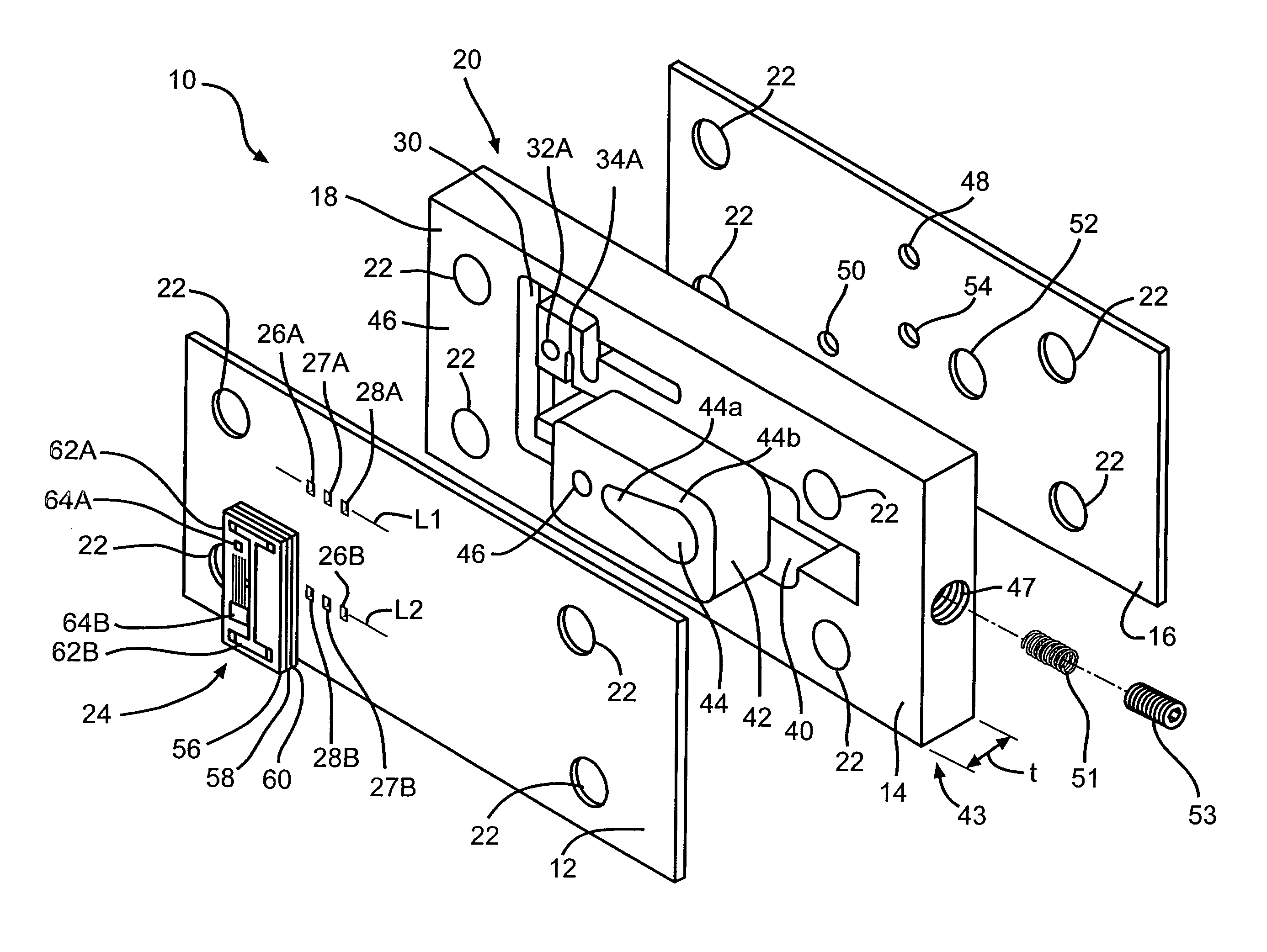
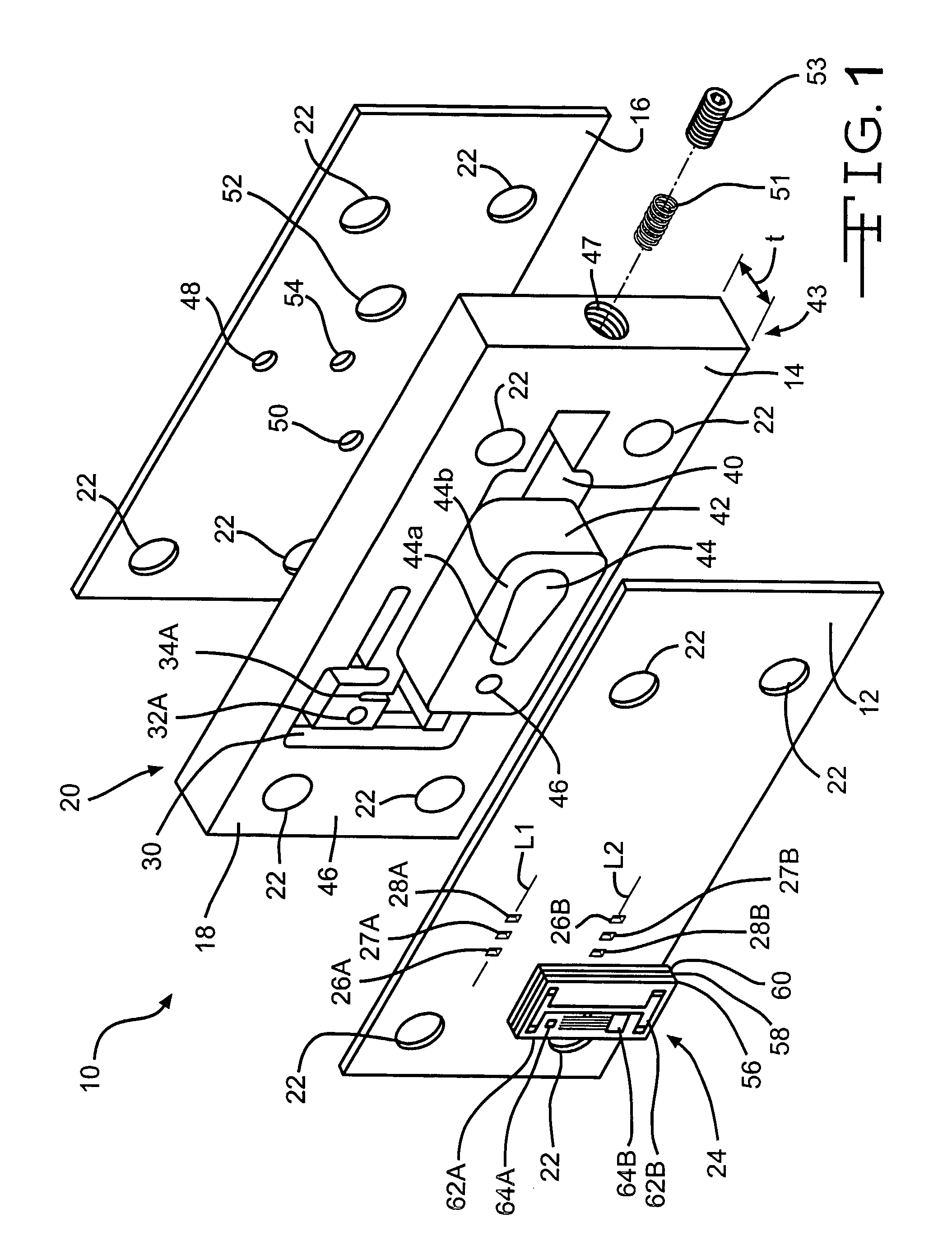
[0029]Referring now to the drawings, there is illustrated in FIG. 1 a valve assembly, indicated generally at 10, according to the present invention. The valve assembly includes a first layer (cover plate) 12, a second layer (center plate) 14, and a third layer (port plate) 16. As will be described in greater detail below, the first layer 12, having a substantially rectangular shape, is a cover plate having a plurality of openings formed therethrough, and having a microvalve 24 attached thereto. The second layer 14 has a substantially rectangular shape and a size that corresponds to the first layer 12, and also includes a plurality of openings formed therethrough, as well as a plurality of channels formed on both the front surface 18 and back surface 20 of the second layer 14, as will be described in more detail below. The third layer 16, having a substantially rectangular shape and a size that corresponds to the first layer 12 and the second layer 14, also includes a plurality of op...


PUM


Abstract

A microvalve device includes a pilot valve and a pilot operated valve. The pilot valve includes a first layer having openings and a second layer having a chamber in communication with the openings, and a movable member for controlling fluid flow. The pilot operated valve includes three plates. Two the openings, and pressure apply and release channels in communication with a spool portion of the pilot operated valve. The spool is movable to allow from a second fluid source to a load. The third plate includes a first source port in communication with a first fluid, the pressure apply and release channel, one of the first plate ports, one of the openings, a first port in communication with a first reservoir, a second port is in communication with the second fluid source and a load port in communication with a load.

Description

[0001]The present invention relates in general to control valves and to semiconductor electromechanical devices, and in particular, to a micromachined control valve for a variable displacement gas compressor.[0002]MEMS (MicroElectroMechanical Systems) is a class of systems that are physically small, having features with sizes in the micrometer range. These systems have both electrical and mechanical components. The term “micromachining” is commonly understood to mean the production of three-dimensional structures and moving parts of MEMS devices. MEMS originally used modified integrated circuit (computer chip) fabrication techniques (such as chemical etching) and materials (such as silicon semiconductor material) to micromachined these very small mechanical devices. Today there are many more micromachining techniques and materials available. The term “microvalve” as used in this application means a valve having features with sizes in the micrometer range, and thus by definition is a...

Claims


Application Information

Patent Timeline
IPC IPC(8): F16K31/00
CPCF16K99/0001F16K99/0011F16K2099/0098F16K99/0044F16K2099/008F16K99/0034F16K31/00F16K31/12
Inventor FULLER, EDWARD NELSON
Owner MICROSTAQ
Learn More