
Vision enhancement apparatus to improve both near and far vision

Active Publication Date: 2008-02-14
RESIDENT ARTIST STUDIO
View PDF5 Cites 26 Cited by
  • Summary
  • Abstract
  • Description
  • Claims
  • Application Information

AI Technical Summary

Benefits of technology

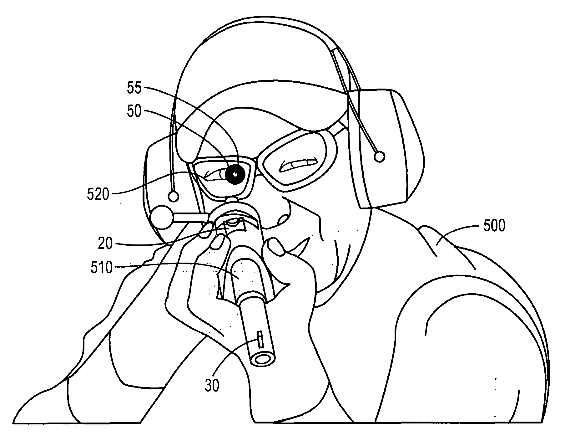
[0009]A small aperture in an opaque material is attached to a pair of glasses worn by the person aiming a firearm. The small aperture collimates the light reflected from the rear sight, the front sight, and the target so that the light from each passes through only a small area of the lens of the person's eye on its way the person's retina. The opaque material is spoken of as a collimator, and the light is collimated by the aperture. Accordingly, only a small area of the person's lens, and then retina, is illuminated by a cone of light rays passing through the aperture. Accordingly, all of the light is rendered into focus on the person's retina. The person can then see all three, the rear sight, the front sight, and the target together. The person can then accurately aim the firearm.

Problems solved by technology

A person who cannot properly accommodate the lens of his / her eye to focus simultaneously to the rear sight, the front sight, and the target is unable to accurately aim the rifle.
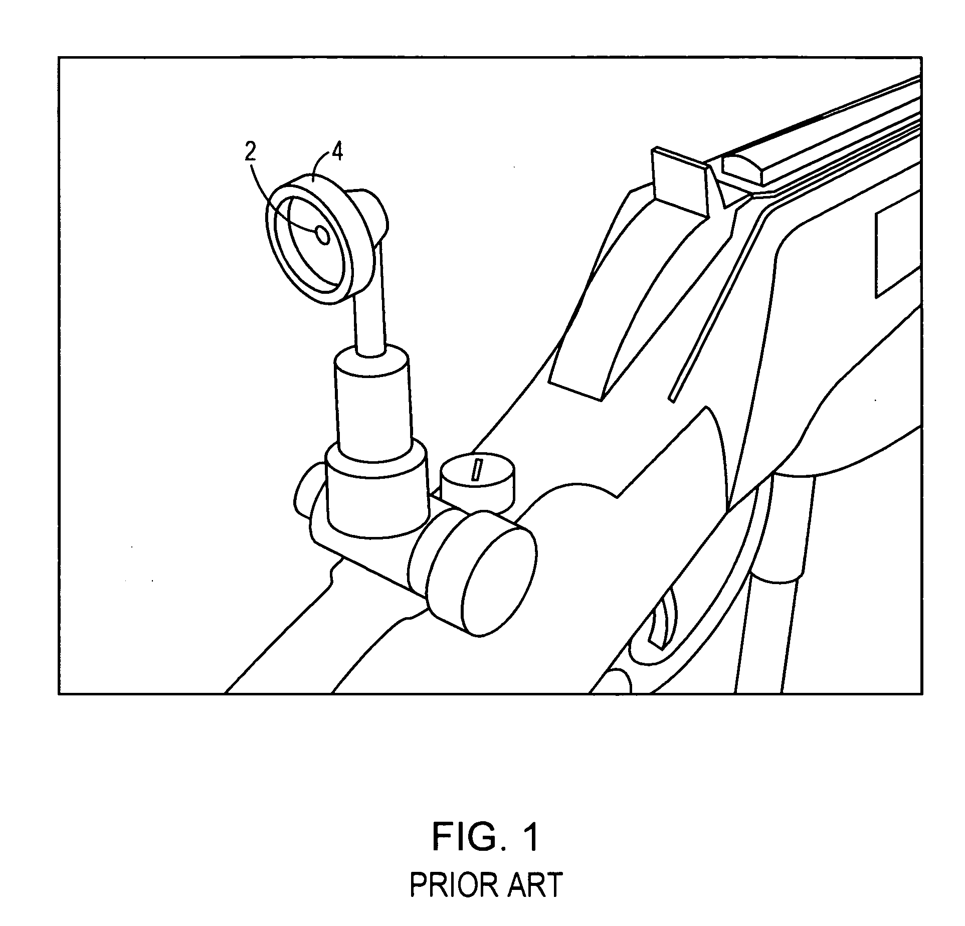
However, a telescope is a complicated attachment to a rifle, and so does not solve the problem of using open sights by a person who is unable to simultaneously visualize a rear open sight, a front sight, and the target.
Further, telescope sights are expensive, and when a person owns several rifles, the cost of a telescope sight for each becomes prohibitive.
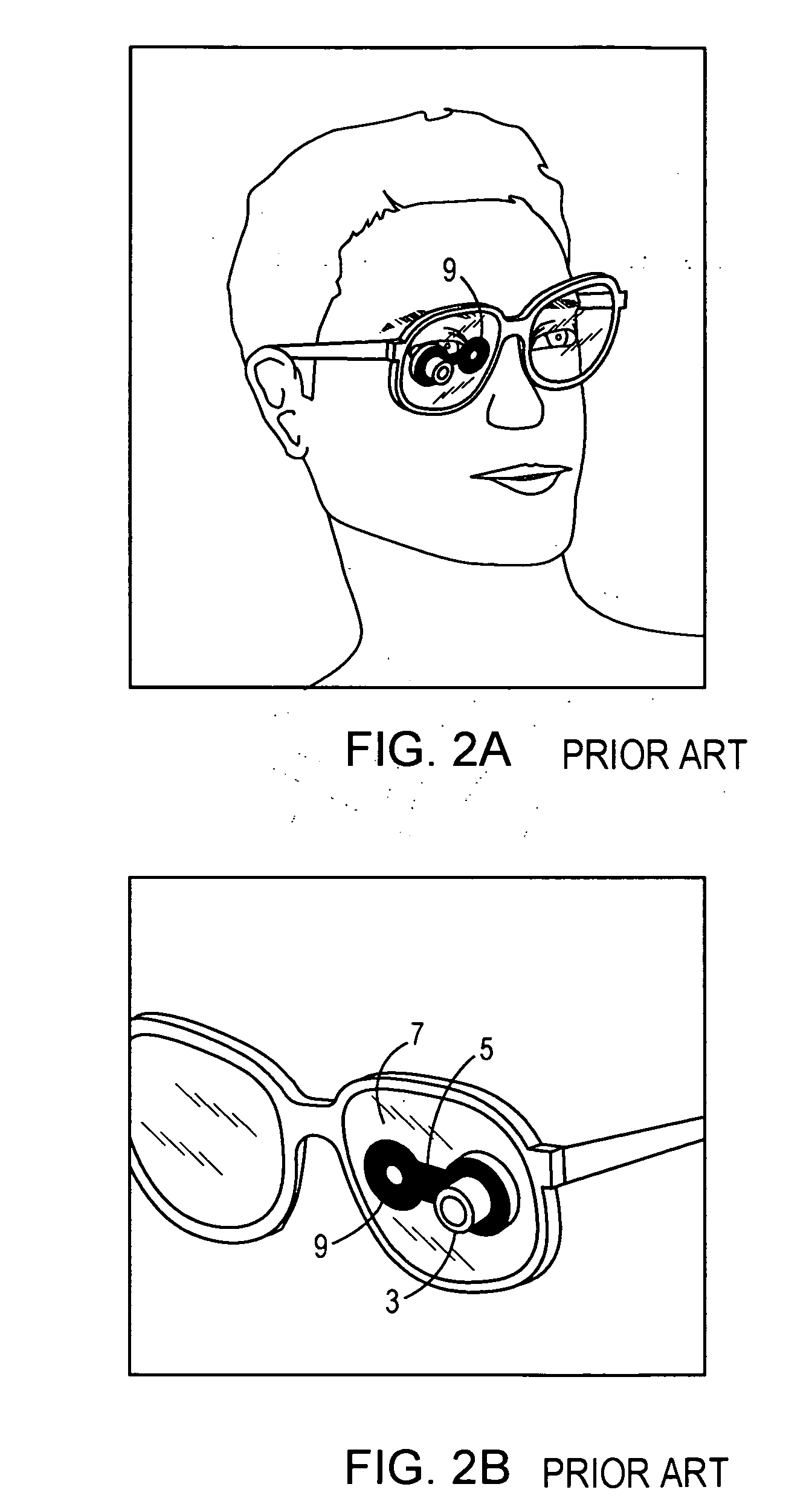
The suction cups refract light and are very distracting to the person trying to aim the firearm.
When a firearm is equipped with open sights, such as a “notch” type rear sight and a “post” type front sight, a person who is either near-sighted or far-sighted has difficulty, and often finds it impossible, to visualize both the rear sight and the front sight, along with the intended target.
Accordingly, the person has great difficulty in aiming the firearm.
The problem of a person with impaired vision, such as either nearsightedness or far-sightedness, to aim a firearm equipped with open sights has not been solved.

Method used


Image

  • Vision enhancement apparatus to improve both near and far vision
  • Vision enhancement apparatus to improve both near and far vision
  • Vision enhancement apparatus to improve both near and far vision

Examples


Embodiment Construction

[0036]Turning now to FIG. 4, a side view schematic diagram of use of the invention is shown. A firearm barrel 10 has a rear open iron sight 20 and a post front sight 30. It is intended to aim the firearm with barrel 10 at target 40. The inventive optical device 50, hereinafter referred to as an “Eye Pal”, is attached to a front surface 60 of a lens 65 of eyeglasses worn by a person (not shown) aiming the firearm at target 40. The words “Eye Pal” are a trademark of the inventor Charles L. Summers, doing business as Resident Artist. The person's eye 70 has the pupil 75 aligned along sight line 80 (indicated by a dashed line) through an aperture 55 of the Eye Pal 50. Also, the line of sight 80 passes through the rear sight 20 and across the top of post sight 30, and extends beyond barrel 10 of the firearm to intersect the target 40. The rear sight 20 and front sight 30 are adjusted so that a bullet fired by the firearm with barrel10 will travel along a Galilean trajectory (not shown) a...


PUM


Abstract

A method for aiming a firearm by a person is disclosed. A collimator of static cling vinyl is attached to a lens of eyeglasses worn by the person. The collimator has an aperture formed in opaque material. A sight line is generated from an eye of the person through the aperture of the collimator, through a rear sight of the firearm, across a front sight of the firearm, and to the target. The aperture of the collimator optically clears the vision of the eye of the person to aid in the person's simultaneous visualization of the rear sight, the front sight, and the target.

Description

FIELD OF THE INVENTION[0001]This invention relates to vision enhancement apparatus, and in particular to simultaneous improvement of both near and far vision. For example, the vision enhancement is applicable to improved sighting of firearms, where it is important for a person aiming firearms to simultaneously visualize a rear sight, a front sight, and the target. The rear sight is in the person's near vision, the front sight is in the person's intermediate vision, and the target is in the person's far vision. A person who is either near-sighted or far-sighted is greatly helped by the simplicity of the present invention.BACKGROUND OF THE INVENTION[0002]Many ideas have been applied to solve the problem of a person with impaired vision, such as either near-sightedness or far-sightedness, to aim a firearm. Aiming, for example, a rifle equipped with open sights requires that the person simultaneously visualize a rear sight, a front sight, and the target. The rear sight may be an open ir...

Claims


Application Information

Patent Timeline
IPC IPC(8): G02C7/00F41G1/00
CPCF41G1/00G02C7/16G02C5/003
Inventor SUMMERS, CHARLES L.
Owner RESIDENT ARTIST STUDIO
Learn More