
Method and apparatus for automatically controlling gas pressure for a plasma cutter

a plasma cutter and automatic control technology, applied in plasma welding apparatus, plasma technique, manufacturing tools, etc., can solve the problems of mechanical regulator use, inefficiency associated with operator's need to adjust gas pressure settings, and construction is not without drawbacks

Active Publication Date: 2008-01-31
ILLINOIS TOOL WORKS INC
View PDF12 Cites 40 Cited by
  • Summary
  • Abstract
  • Description
  • Claims
  • Application Information

AI Technical Summary

Benefits of technology

The present invention provides a plasma cutting system that can dynamically control gas flow in a plasma torch. This is achieved through a proportional valve and pressure sensor arrangement connected to a controller. The controller adjusts the drive signal sent to the proportional valve to regulate gas flow. This results in a more precise and accurate control of gas pressure, which improves the quality and efficiency of plasma cutting operations.

Problems solved by technology

While control of air pressure settings in this manner provides an operator with a great deal of control, such a construction is not without its drawbacks.
One drawback associated with existing gas pressure regulation systems, such as the one described above, is the imprecision associated with the use of mechanical regulators.
Another drawback of existing systems is the inefficiency associated with the operator's need to adjust gas pressure settings.
Suspending one process in order for the operator to check a pressure gauge and adjust the pressure setting for another operation is time consuming and results in overall process inefficiency.

Method used


Image

  • Method and apparatus for automatically controlling gas pressure for a plasma cutter
  • Method and apparatus for automatically controlling gas pressure for a plasma cutter
  • Method and apparatus for automatically controlling gas pressure for a plasma cutter

Examples


Embodiment Construction

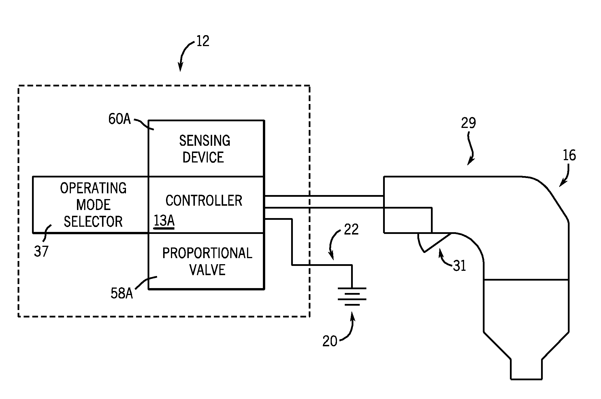
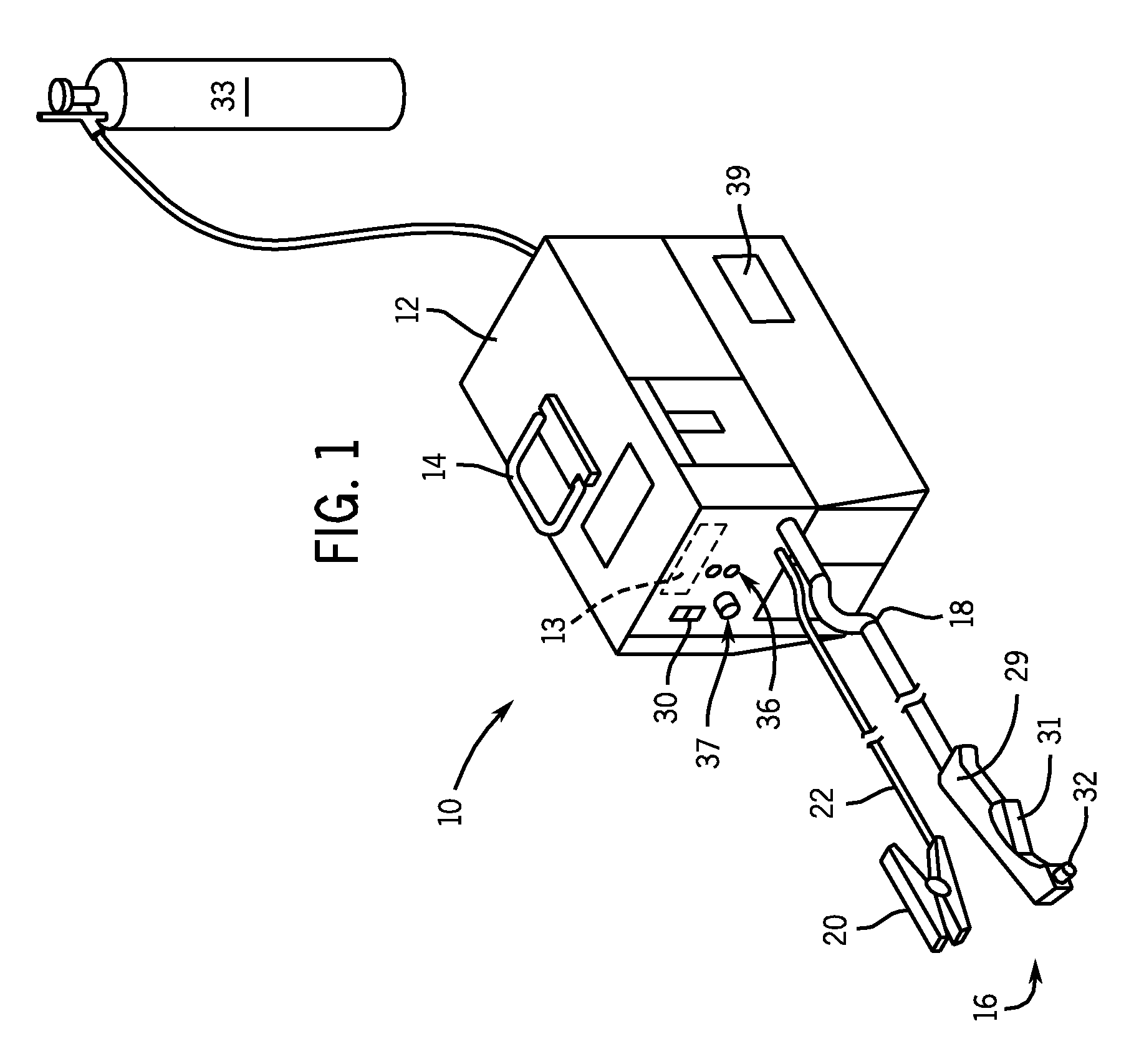
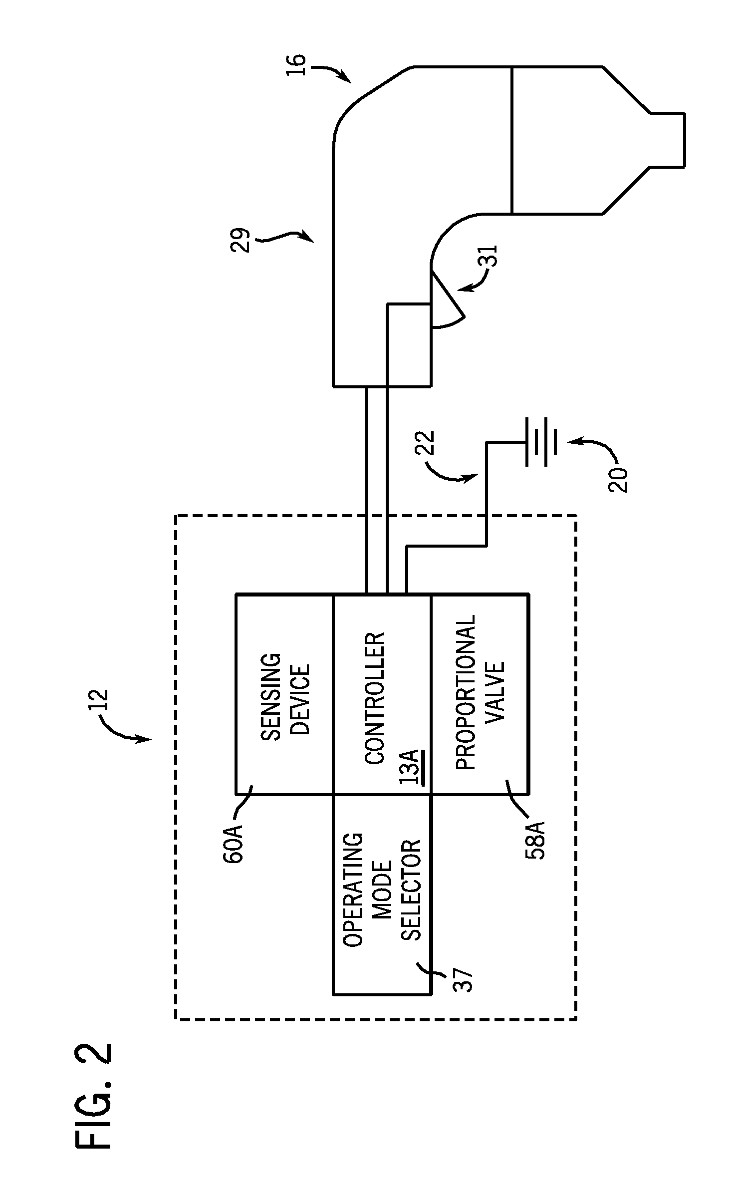
[0019]FIG. 1 shows a plasma cutting system 10 according to the present invention. Plasma cutting system 10 is a high voltage system with open circuit output voltages that typically range from approximately 230 Volts Direct Current (VDC) to over 300 VDC. Plasma cutting system 10 includes a power source 12 to condition raw power and generate a power signal suitable for plasma cutting applications. Power source 12 includes a controller 13 that receives operational feedback and monitors the operation of a plasma cutting system 10. Power source 12 includes a handle 14 to effectuate transportation from one site to another. Connected to power source 12 is a torch 16 via a cable 18. Cable 18 provides torch 16 with power and compressed air or gas, and also serves as a communications link between torch 16 and power source 12. Torch 16 includes a handle portion 29, or torch body, having a trigger 31 thereon and work tip 32 extending therefrom. Although shown as attached to torch 16, it is unde...


PUM

PropertyMeasurementUnit
voltagesaaaaaaaaaa
currentaaaaaaaaaa
voltageaaaaaaaaaa

Abstract

A system for providing a dynamically controlled plasma cutting system. The plasma cutting system includes a proportional valve and a sensing device arrangement and a controller connected to this arrangement. The system is configured to dynamically control gas flow in a plasma torch. The system measures gas pressure at a proportional valve and makes necessary gas pressure adjustments in the system by way of controlling a drive signal sent to the proportional valve to control gas flow.

Description

BACKGROUND OF THE INVENTION[0001]The present invention relates generally to plasma cutting systems and, more particularly, to a method and apparatus for automatically controlling gas pressure for a plasma cutter.[0002]Plasma cutting is a process in which an electric arc and plasma gas are used to cut or gouge a workpiece. Plasma cutters typically include a power source, a gas supply, such as compressed air, and a torch. The torch is constructed to create and maintain the plasma arc. To generate the plasma cutting power, a power source receives an input voltage from a transmission power receptacle or generator and provides output power to a pair of output terminals. One of the output terminals is connected to an electrode and the other is connected to the workpiece. An air supply is used with most plasma cutters to carry and propel the arc to the workpiece and assist in cooling the torch.[0003]In order to operate properly, the plasma torch requires consistent, and preferably controll...

Claims


Application Information

Patent Timeline
Patent Type & Authority Applications(United States)
IPC IPC(8): B23K9/00
CPCB23K10/006H05H1/34H05H1/36
Inventor SALSICH, ANTHONY V.SCHNEIDER, JOSEPH C.ULRICH, JAMES F.
Owner ILLINOIS TOOL WORKS INC
Learn More