
Elevator having second driving device

Inactive Publication Date: 2008-01-31
HIWIN TECH
View PDF8 Cites 5 Cited by
  • Summary
  • Abstract
  • Description
  • Claims
  • Application Information

AI Technical Summary

Benefits of technology

[0010]The primary objective of the present invention is to provide a screw type elevator having a second or auxiliary driving device for moving a screw shaft and / or a carriage and for allowing the carriage to be moved to a safe location when the main or primary driving driving device has become failure.
[0015]One or more bearings may be disposed between the driving nut and the coupling device for allowing the driving nut to be smoothly driven or rotated relative to the coupling device.

Problems solved by technology

However, when the electric power supply is cut off, particularly when earthquakes are occurred, or when the single motor driving means or device is damaged or become failure, the carriage or the elevator car may no longer be moved up and down relative to the elongated structural environment, and may only be energized or moved again when the electric power supply is recovered.

Method used


Image

  • Elevator having second driving device
  • Elevator having second driving device
  • Elevator having second driving device

Examples


Embodiment Construction

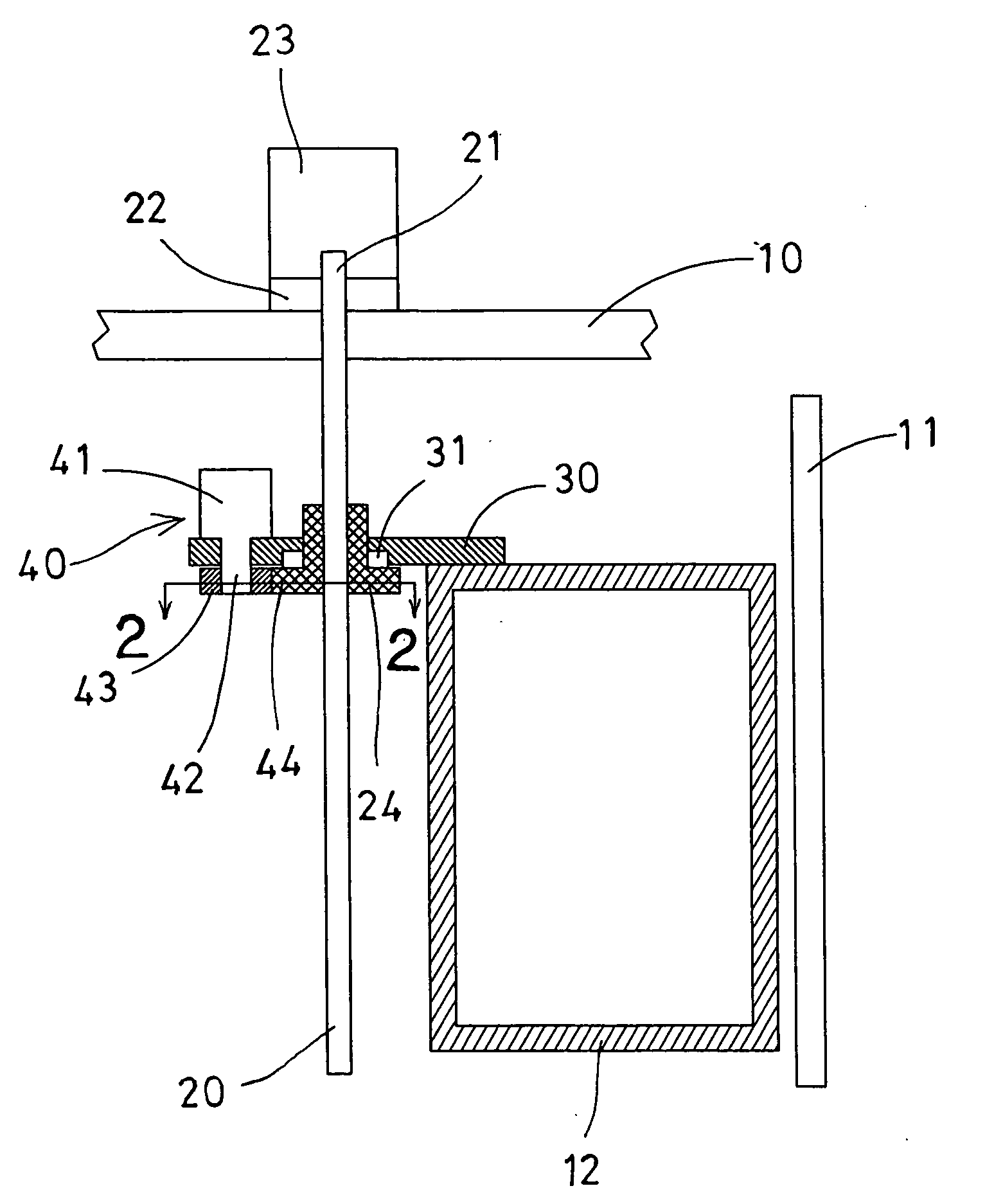
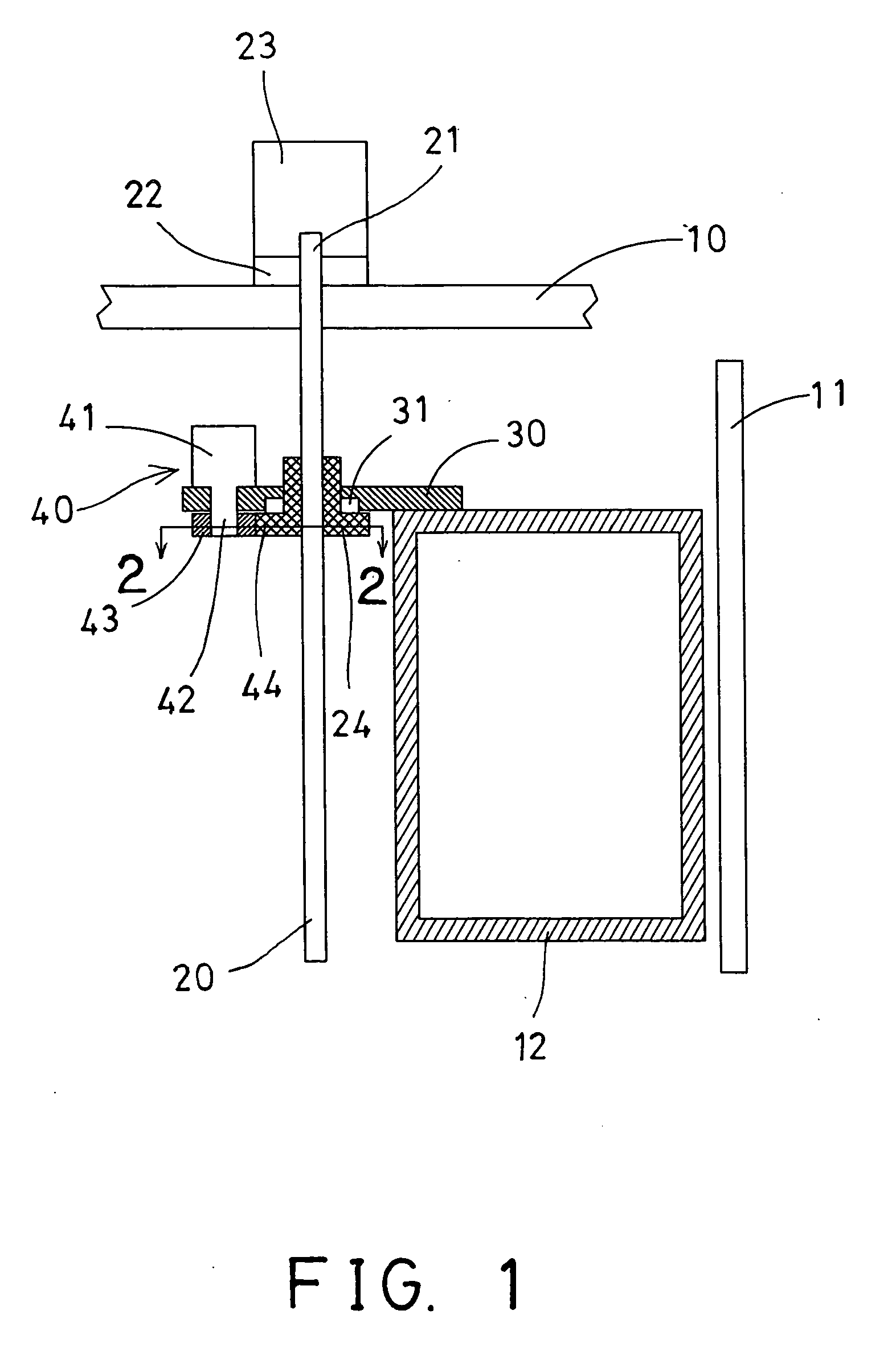
[0019]Referring to the drawings, and initially to FIG. 1, an elevator in accordance with the present invention comprises a ceiling or supporting member 10, one or more guide rails 11 vertically disposed for forming or defining a vertically elongated structural environment, and a carriage or elevator car 12 to be guided to move up and down relative to the supporting member 10 and along the guide rails 11 for moving a payload such as personnel or cargo up and down along the vertically elongated structural environment formed or defined by the vertically disposed guide rails 11. One or more typical wire ropes (not shown) may be selectively or additionally provided and coupled to the carriage or elevator car 12 for safely pulling and suspending the elevator car 12 at selected position.

[0020]A screw shaft or threaded member 20 includes an upper portion 21 vertically and rotatably attached to the supporting member 10 with such as a bearing or supporting device 22, and coupled to a first po...


PUM


Abstract

An elevator includes an elevator car guided to move up and down relative to a supporting member, a screw shaft having an upper end attached to the supporting member, a driving nut rotatably supported in a coupling device and threaded with the screw shaft, one driving device coupled to rotate the screw shaft and to move the driving nut up and down along the screw shaft, and a coupling device rotatably attached onto the driving nut and coupled to the elevator car. Another spare driving device may further be coupled to drive the screw shaft for moving the elevator car to a lower level or a safe location when the driving device has become failure or has damaged.

Description

BACKGROUND OF THE INVENTION[0001]1. Field of the Invention[0002]The present invention relates to a screw shaft for such as an elevator, and more particularly to a screw type elevator having a second or auxiliary driving device for moving a screw shaft and / or a carriage and for allowing the carriage to be moved to a safe location when the main or primary driving device or power has become failure.[0003]2. Description of the Prior Art[0004]Typical elevator systems comprise a carriage for moving a payload such as personnel or cargo traversely along a vertically elongated structural environment, and a finite length framework along which the vertically movable carriage through a guidable yoke slidably traverses, and one or more upright rails for guiding the carriage to move up and down relative to the elongated structural environment.[0005]For example, U.S. Pat. No. 3,381,541 to Thireau et. al. discloses one of the typical elevator systems or transmission devices comprising a carriage gu...

Claims


Application Information

Patent Timeline
IPC IPC(8): B66B9/02
CPCB66B5/027B66B9/025Y10T74/18576Y10T74/186Y10T74/18624
Inventor KUO, CHANG HSIN
Owner HIWIN TECH
Learn More