
Color filter substrate, color liquid crystal display device using the same, and method for repairing the same

a technology of color filter substrate and color liquid crystal display device, which is applied in the direction of pretreatment surfaces, coatings, instruments, etc., can solve the problems of foreign substance entering the colored layer of pixels, affecting the quality of display, and affecting the appearance quality of the display device, so as to reduce the number of inspection processes, reduce the number of fabrication processes, and facilitate the repair

Inactive Publication Date: 2008-01-24
NEC LCD TECH CORP
View PDF14 Cites 3 Cited by
  • Summary
  • Abstract
  • Description
  • Claims
  • Application Information

AI Technical Summary

Benefits of technology

[0015]In view of the foregoing and other exemplary problems, drawbacks, and disadvantages of the related art methods and structures, the present invention provides a color filter substrate, a color liquid crystal display device using the color filter substrate, and a method for repairing the same, which makes it possible to more easily repair a defect that occurs when a foreign substance enters a display unit.
[0018]Accordingly, with the design and the method as described above, the color filter substrate, the color liquid crystal display device using the color filter substrate, and the method for repairing the same of the present invention produces an effect that a defect that occurs when a foreign substance enters a display unit can be easily repaired. Further, in the present invention, since the number of inspection processes can be reduced, and since it is not necessary to newly form a colored layer and an ITO film after repair, the present invention produces another effect that the number of fabrication processes can be reduced and simplified.

Problems solved by technology

However, there is a problem that a foreign substance may enter the colored layers for pixels when fabricating such a color filter substrate.
The entering of such a foreign substance could cause a problem such as a short circuit between electrodes of the color filter substrate and a counter substrate, and degradation of display quality.
Then, after the repair, the ITO film needs to be formed on the repaired substrate, but a defect such as the entering of a foreign substance may occur again in this ITO film formation process.
As a result, any of the above-described repairing methods has a problem that such necessity of many inspections may cause an increase in costs.
Accordingly, using the above-described repairing methods may increase the number of fabrication processes, which results in a problem of high cost.
Further, when a defect is found on an ITO film in a final inspection, an ITO film of an area containing the defect also needs to be removed.
Accordingly, using the above-described repairing methods may increase the number of fabrication processes, which result in a problem of high cost.
Accordingly, the burden of repair is also increased, which results in a problem of high cost.

Method used


Image

  • Color filter substrate, color liquid crystal display device using the same, and method for repairing the same
  • Color filter substrate, color liquid crystal display device using the same, and method for repairing the same
  • Color filter substrate, color liquid crystal display device using the same, and method for repairing the same

Examples


first embodiment

[0033]a color filter substrate, a color liquid crystal display device using the color filter substrate, and a method for repairing the same of the present invention will be described below.

[0034]First of all, a design of a color filter substrate according to the first embodiment of the present invention is described below in detail.

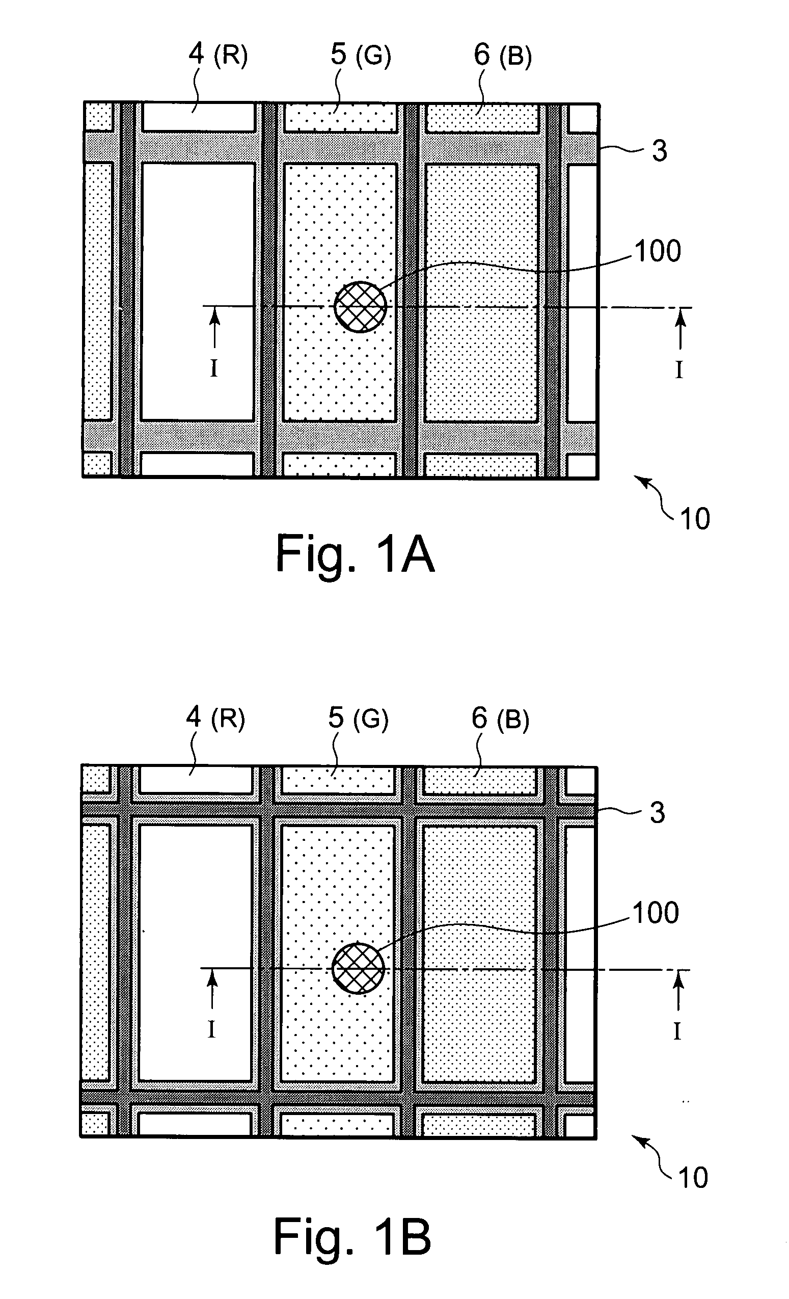
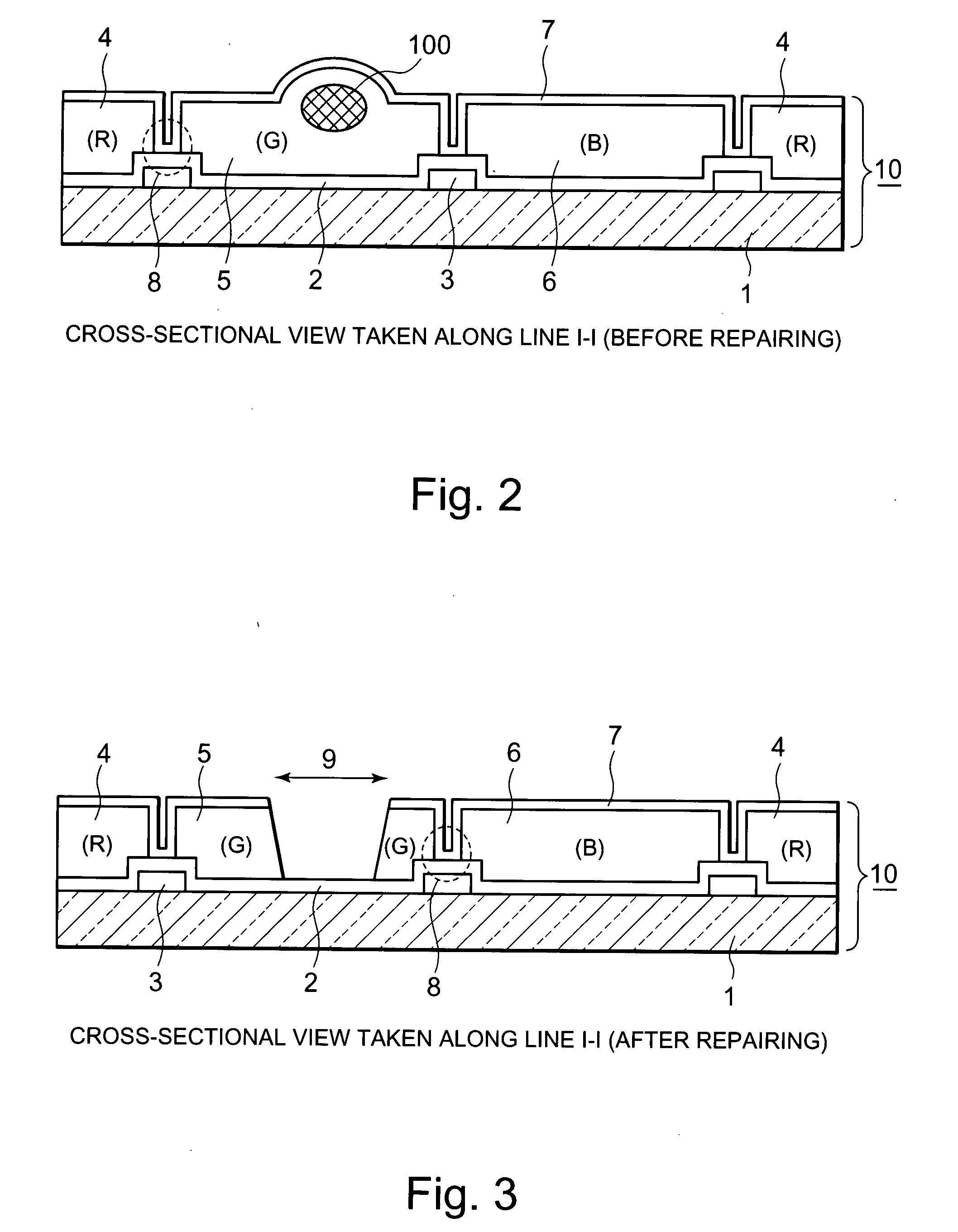
[0035]FIGS. 1A and 1B each show a partial plan view of a color filter substrate according to the first embodiment of the present invention. Further, FIG. 1A shows a type of a color filter substrate in which a colored layer is formed in stripe, and FIG. 1B shows another type of a color filter substrate in which a colored layer is formed in lattice. FIG. 2 shows a cross-sectional view taken along the line I-I of each of the color filter substrates in FIGS. 1A and 1B before repairing the same. In addition, each of these drawings shows a state in which a foreign substance has mixed into a colored layer.

[0036]In a color filter substrate 10, a black matrix (her...

second embodiment

[0055]Subsequently, a color filter substrate according to the present invention will be described below.

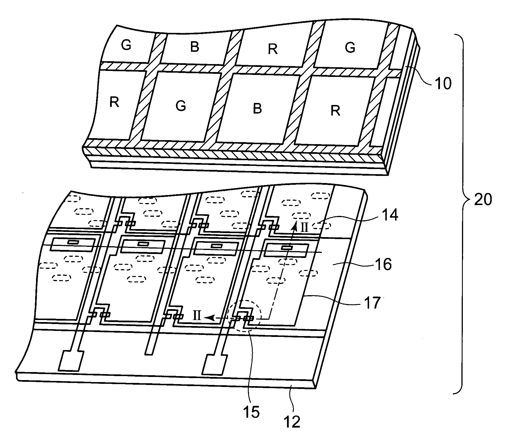
[0056]FIG. 6A shows a plan view of a color filter substrate according to a second embodiment of the present invention. FIG. 6B shows a cross-sectional view taken along the line II-II of FIG. 6A.

[0057]In the first embodiment shown in FIG. 2, a connection between the upper ITO film and the lower ITO film is established on the BM in the display unit within a pixel area. On the other hand, as shown in FIG. 6B, in the second embodiment, an upper ITO film 27 and a lower ITO film 22 do not have a structure in which these films 27 and 22 are electrically connected to each other within a display unit 31, which is a pixel area. Instead of that, the upper ITO film 27 and the lower ITO film 22 have a structure in which these films 27 and 22 are electrically connected to each other in a connection part 28 in a peripheral part 32 of the display unit 31. Thus, the upper ITO film 27 and the lower...

third embodiment

[0060]Next, a color filter substrate according to the present invention will be described below.

[0061]FIG. 7 shows a cross-sectional view of a color filter substrate of the third embodiment. In this third embodiment, an overcoat layer 48 is formed over colored layers 44 to 46 so as to flatten the surface. The material of the overcoat layer 48 is usually photo-curing resin or heat-curing resin. When using photo-curing resin, a through-hole for connection can be easily formed at a specific position. Thus, in this third embodiment, an upper ITO film 47 and a lower ITO film 42 are connected to each other by using the through-hole. To be more precise, a through-hole part 49 is formed on the overcoat layer 48 on a peripheral part 52 as shown in FIG. 7; and the upper ITO film 47 and the lower ITO film 42 are electrically connected to each other in this through-hole part 49.

[0062]In this third embodiment also, repair is performed using the same design and fabrication method as those of the ...


PUM

PropertyMeasurementUnit
transparentaaaaaaaaaa
voltageaaaaaaaaaa
plurality of colorsaaaaaaaaaa

Abstract

A color filter substrate includes a transparent substrate, a lower transparent electrode disposed on the transparent substrate, a colored layer disposed on the lower transparent electrode in a display area, and an upper transparent electrode disposed on the colored layer and electrically connected to the lower transparent electrode.

Description

BACKGROUND OF THE INVENTION[0001]1. Field of the Invention[0002]The present invention relates to a color filter substrate, a color liquid crystal display device using the color filter substrate, and a method for repairing the same. In particular, the present invention relates to a design and a method that permits repairing a defect that occurs when a foreign substance enters a display unit.[0003]2. Description of the Related Art[0004]Color liquid crystal display devices normally include a color filter substrate provided with colored layers of a plurality of colors, an array substrate facing the color filter substrate, and a liquid crystal layer filled and sealed between these substrates. Colors are displayed by controlling transmittance of a part of the liquid crystal layer at a position corresponding to each of the colored layers.[0005]FIG. 8 is a cross-sectional view of a color filter substrate for a conventional color liquid crystal display device. The conventional color filter s...

Claims


Application Information

Patent Timeline
Patent Type & Authority Applications(United States)
IPC IPC(8): G02F1/1335B05D3/00
CPCG02F1/1309G02F1/133514G02F2201/121G02F1/13G02F1/1335
Inventor SHIMIZU, TAKEYA
Owner NEC LCD TECH CORP
Learn More