Economical filter changing apparatus and method for electrical discharge machines and other applications

a technology of filter changing apparatus and electrical discharge machine, which is applied in the direction of filtration separation, separation process, manufacturing tools, etc., can solve the problems of heavy and expensive metal or high-strength plastic components (end caps and wrappers) needed to achieve this approach, and achieve the effect of reliable and cost-effectiv

Inactive Publication Date: 2008-01-17
HOFF ENG
View PDF10 Cites 2 Cited by
  • Summary
  • Abstract
  • Description
  • Claims
  • Application Information

AI Technical Summary

Benefits of technology

[0010]A pair of opposing swing arms, each having one end pivotally connected to a filter cabinet or other suitable base and another end pivotally connected to a point on the exterior surface of the cylindrical housing, facilitate a first state, wherein the housing and filter are vertically oriented with the bottom opening of the filter sealed against the inlet fitting for filtering operation, and a second state, wherein the housing is pivoted such that the top is oriented downwardly allowing the filter to disengage from the inlet fitting and slide out of the housing.

Problems solved by technology

The metal or high strength plastic components (end caps and wrappers) necessary to this approach are both expensive and heavy.

Method used


Image

  • Economical filter changing apparatus and method for electrical discharge machines and other applications
  • Economical filter changing apparatus and method for electrical discharge machines and other applications
  • Economical filter changing apparatus and method for electrical discharge machines and other applications

Examples


Embodiment Construction

[0027]For the purpose of understanding the invention, reference will now be made to the embodiment illustrated in the drawings. It should be understood that no limitation of the invention's scope is thereby intended. The specification relates primarily to filtering the common EDM fluids but its principles could be extended to include other flowable substances including, but not limited to, machining fluids, coolants, and other industrial and process fluids. Further applications of the principles of the invention as illustrated would normally occur to one skilled in the art to which the invention relates.

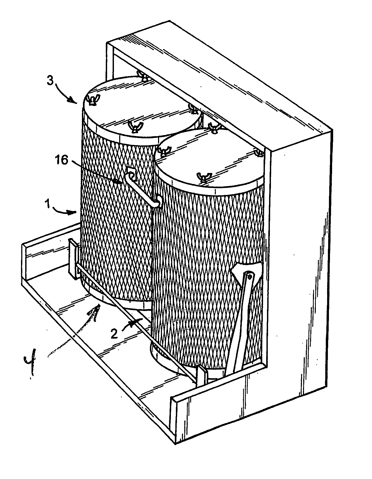
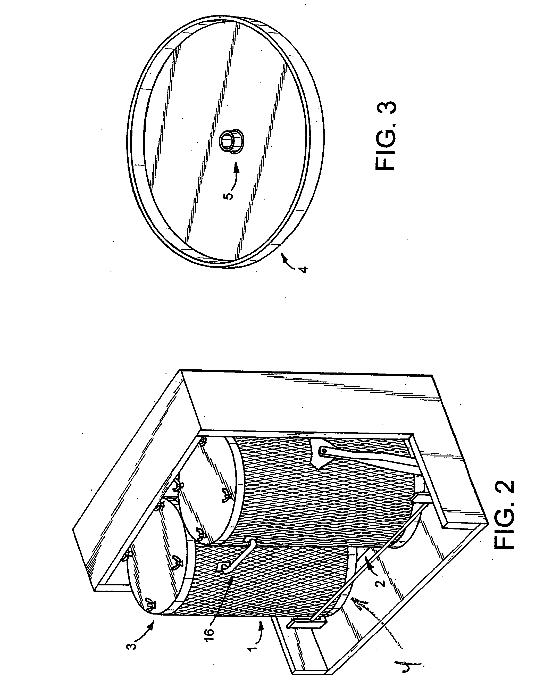
[0028]This specific preferred embodiment is a retrofit filter machine adapted for use on a EDM wherein a large portion of the filter machine consists of fabricated metal components that may be re-used indefinitely.

[0029]FIG. 2 is a perspective drawing of the preferred embodiment of the invention in place within a filter cabinet. The system comprises at least one structural housing to...


PUM


Abstract

A reliable, cost effective system and method are disclosed for exchanging fluid-filtration filters associated with electrical discharge machines (EDMs) and other applications. The system is compatible with filters of the type receiving fluid to be filtered from the inside out. The basic system comprises a housing to receive the filter, the housing having a top that opens and a bottom cap with an interior inlet fitting coupled to a supply line carrying fluid to be filtered. A pair of opposing swing arms, each having one end pivotally connected to a filter cabinet or other suitable base and another end pivotally connected to an opposing side of the housing, facilitate a first state, wherein the housing and filter are vertically oriented with the bottom opening of the filter sealed against the fitting for filtering operation, and a second state, wherein the housing is pivoted such that the top is oriented downwardly allowing the filter to disengage from the fitting and slide out of the housing. In the preferred embodiment a stop member engages with the swing arms to facilitate an intermediate position wherein the housing is tilted for the loading of a new filter.

Description

FIELD OF THE INVENTION[0001]The invention relates generally to filtration and fluid control. More particularly, the invention relates to industrial filtration systems for coolants and metal working fluids.BACKGROUND OF THE INVENTION[0002]Prior art systems used to filter machine tool working fluids conventionally include an electric motor driven pump, one or more dirty side tank(s) for collecting the contaminated working fluid, a filter, a clean side tank or compartment, and (usually) a second pump to return the clean filtrate back to one or more machine tools. Representative systems are disclosed in U.S. Pat. No. 2,276,824 to Carruthers and U.S. Pat. No. 4,282,094 to Mitchell.[0003]The industrial coolant filtering systems in U.S. Pat. No. 4,865,724 to Brandt et al., U.S. Pat. No. 5,417,849 to McEwen et al., and U.S. Pat. No. 6,485,634 to Warren et al. share these characteristics. Also described in the prior art are auxiliary and / or portable filter systems for recycling machine tool ...

Claims


Application Information

Patent Timeline
IPC IPC(8): B01D35/28
CPCB01D29/52B01D35/30B01D29/96B01D29/965
Inventor DOYLE, EDWARD M.DOYLE, E. MICHAELARGUE, DANIEL E.
Owner HOFF ENG
Why Eureka
Try Eureka