
Dynamic Decoding of Binaural Audio Signals

a binaural audio and dynamic decoding technology, applied in the field of spatial audio coding, can solve the problems of omitting the control of audio image, content creation does not have any knowledge of the available hrtf, and significant differences in perceived audio images, so as to achieve the effect of minimizing the bitrate of control information

Active Publication Date: 2008-01-10
NOKIA TECHNOLOGLES OY
View PDF11 Cites 99 Cited by
  • Summary
  • Abstract
  • Description
  • Claims
  • Application Information

AI Technical Summary

Benefits of technology

The invention provides a method for making dynamic binaural control available even if the decoder contains only a limited set of HRTF filters. The method involves inputting a parametric audio signal and generating a binaural audio signal by searching a set of head-related transfer function filters in a stepwise motion. The method allows for a minimization of the bitrate of control information and reliable utilization of dynamic control. Additionally, the invention provides a method for generating a parametric audio signal by inputting a multi-channel audio signal and generating corresponding side information including channel configuration information for controlling audio source locations in a synthesis of a binaural audio signal. This allows for control of the use of incremental steps in the binaural downmix.

Problems solved by technology

Therefore, the content creation does not have any knowledge on the available HRTF filter database in the binaural decoder.
As a result, the decoder may omit the audio image control due to an incompatible HRTF filter set, whereby the perceived audio image may differ significantly from what was intended by the content creator.

Method used


Image

  • Dynamic Decoding of Binaural Audio Signals
  • Dynamic Decoding of Binaural Audio Signals
  • Dynamic Decoding of Binaural Audio Signals

Examples


Embodiment Construction

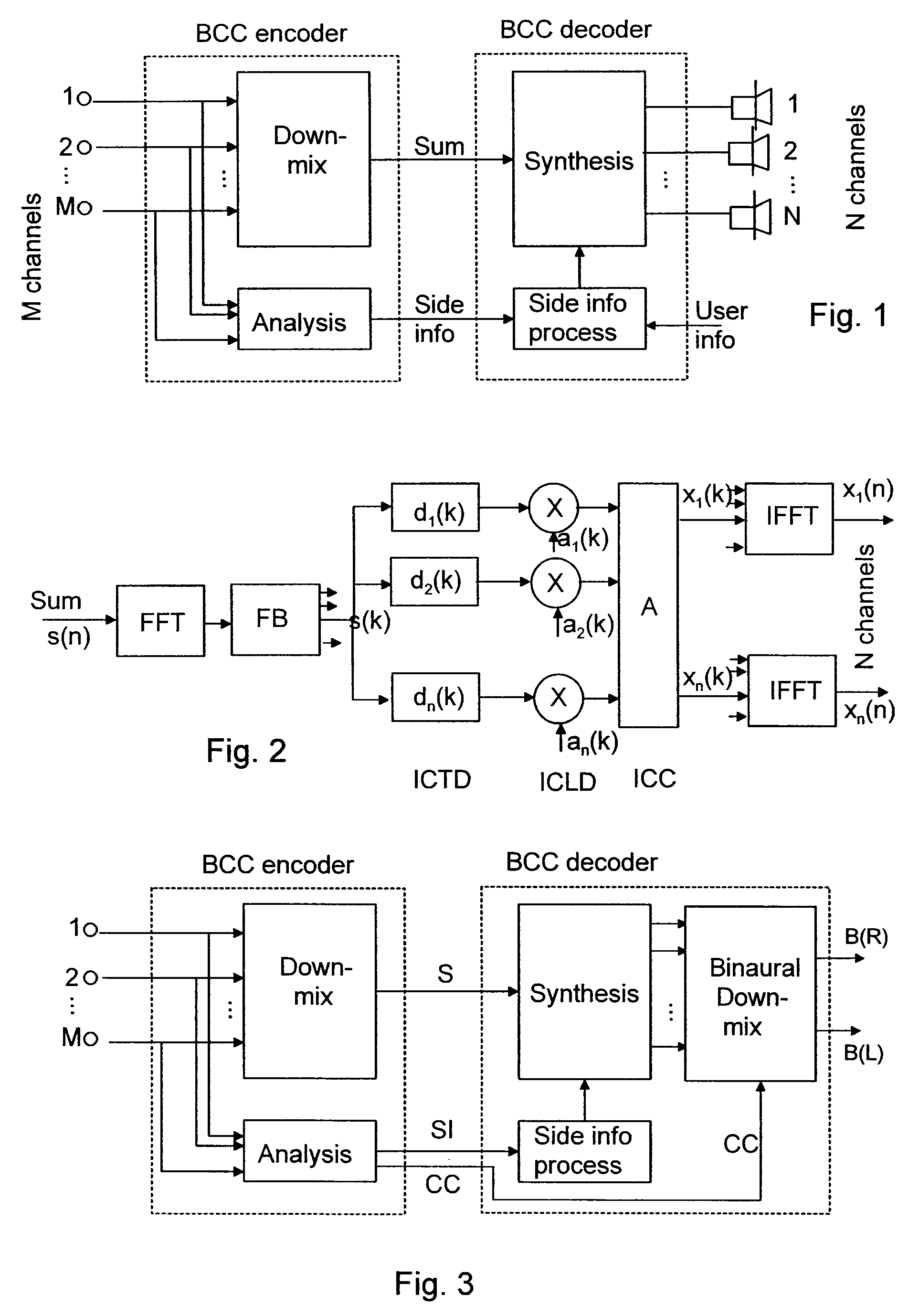
[0024]In order to make the embodiments more tangible, the binaural decoder disclosed in the above-mentioned document “Further information on binaural decoder functionality”, by Ojala P., Jakka J., and its operation is explained briefly herein. As background information for the binaural decoder, the concept of Binaural Cue Coding (BCC) is first briefly introduced as an exemplified platform for implementing the encoding and decoding schemes according to the embodiments. It is, however, noted that the invention is not limited to BCC-type spatial audio coding methods solely, but it can be implemented in any audio coding scheme providing at least one audio signal combined from the original set of one or more audio channels and appropriate spatial side information. For example, the invention may be utilized in MPEG surround coding scheme, which as such takes advantage of the BCC scheme, but extends it further.

[0025]Binaural Cue Coding (BCC) is a general concept for parametric representati...


PUM


Abstract

Inputting of a parametrically encoded audio signal comprising at least one combined signal of a plurality of audio channels and one or more corresponding sets of side information describing a multi-channel sound image and including channel configuration information is shown along with deriving, from the channel configuration information, audio source location data describing at least one of horizontal and vertical positions of audio sources in the binaural audio signal; selecting, from a predetermined set of head-related transfer function filters, a left-right pair of head-related transfer function filters matching closest to the audio source location data, wherein the left-right pair of head-related transfer function filters is searched in a stepwise motion in a horizontal plane; and synthesizing a binaural audio signal from the at least one processed signal according to side information and the channel configuration information.

Description

BACKGROUND OF THE INVENTION[0001]The present invention relates to spatial audio coding, and more particularly to controlling dynamic decoding of binaural audio signals.[0002]In spatial audio coding, a two / multi-channel audio signal is processed such that the audio signals to be reproduced on different audio channels differ from one another, thereby providing the listeners with an impression of a spatial effect around the audio source. The spatial effect can be created by recording the audio directly into suitable formats for multi-channel or binaural reproduction, or the spatial effect can be created artificially in any two / multi-channel audio signal, which is known as spatialization.[0003]It is generally known that for headphones reproduction artificial spatialization can be performed by HRTF (Head Related Transfer Function) filtering, which produces binaural signals for the listener's left and right ear. Sound source signals are filtered with filters derived from the HRTFs corresp...

Claims


Application Information

Patent Timeline
Patent Type & Authority Applications(United States)
IPC IPC(8): H04R5/00
CPCH04S3/02H04S2420/03H04S2420/01H04S2400/01G10L19/008G10L19/02H04S3/00H03M7/30
Inventor OJALA, PASITURKU, JULIA
Owner NOKIA TECHNOLOGLES OY
Learn More