
Drapes

a drapery and drapery technology, applied in the field of drapes, can solve the problems that drapes are not ideally suited for tracheostomy or other procedures

Inactive Publication Date: 2008-01-10
SMITHS GRP PLC
View PDF9 Cites 60 Cited by
  • Summary
  • Abstract
  • Description
  • Claims
  • Application Information

AI Technical Summary

Problems solved by technology

Presently available drapes are not ideally suited to tracheostomy or other procedures in the region of the neck.

Method used


Image

  • Drapes
  • Drapes

Examples


Embodiment Construction

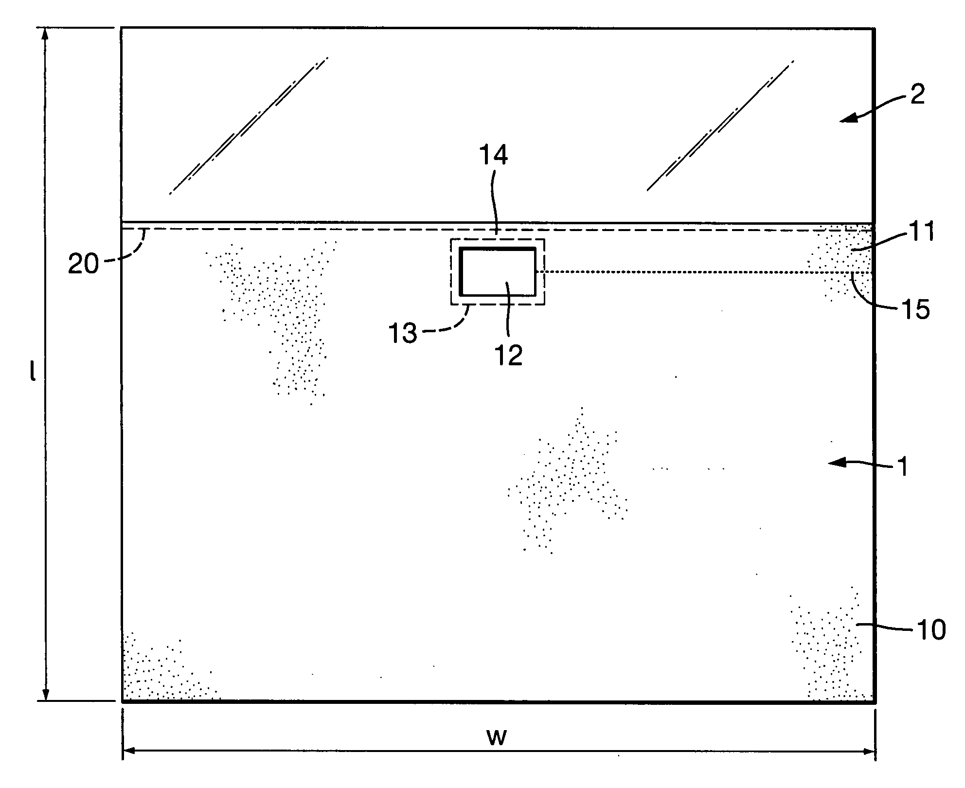
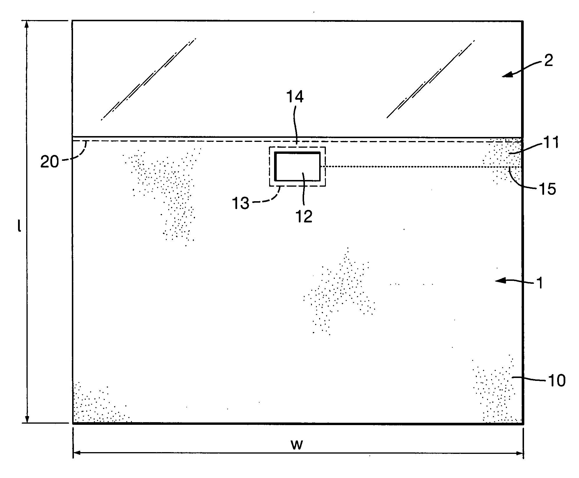
[0010] The drape is rectangular with a length l of 140 cm and a width w of 160 cm. The drape is divided into a body region 1 and a head region 2.

[0011] The body region 1 is formed of a soft, spun-woven, flexible, drapeable sheet of an opaque, water-repellent single ply material. The body region 1 extends for 100 cm with its lower end 10 located, in use, in the region of the groin of the patient, and its upper end 11 located in the region of the chin. The body region 1 extends across the entire width w of the drape, this width being sufficient to cover the upper part of the body and hang down a short distance at opposite sides of the patient. The body region 1 is interrupted by an incise window 12 in the form of an open aperture cut through the material of the region and located a few centimetres from the edge of the upper end 11. The incise window 12 is located centrally across the width of the drape and is rectangular in shape being 10 cm wide and 15 cm long. The window could be o...


PUM


Abstract

A surgical drape for use in tracheostomy procedures has a main body region and a transparent region arranged to extend over the head of the patient. An incise aperture is formed in the body region close to the transparent head region. An adhesive border around the patient side of the aperture enables the drape to be secured to the skin around the tracheostomy. A perforated tear line extends laterally from the aperture to the edge of the drape to enable the drape to be torn easily so that it can be removed from around any tubing projecting through the aperture.

Description

BACKGROUND OF THE INVENTION [0001] This invention relates to drapes. [0002] The invention is more particularly concerned with drapes during surgical procedures on the neck, such as tracheostomy procedures. [0003] Drapes are commonly used during surgical procedures to cover regions around the surgical site so as to protect the site from contamination. The drapes take many different forms. U.S. Pat. No. 4,384,573 describes a drape covering the entire body and having windows in the region of the abdomen and the face. U.S. Pat. No. 5,592,952 describes a drape with an aperture through which a limb of the patient is extended. U.S. Pat. No. 6,843,252 describes a drape held above the patient by a maintenance cover. U.S. Pat. No. 3,349,765 describes a rolled drape. U.S. Pat. No. 3,260,260 describes a drape with an adhesive layer. U.S. Pat. No. 6,742,522 and U.S. Pat. No. 5,803,086 describe incise drapes through which a cut can be made. U.S. Pat. No. 5,341,821 describes a drape that hangs dow...

Claims


Application Information

Patent Timeline
Patent Type & Authority Applications(United States)
IPC IPC(8): A61B19/08
CPCA61B2019/085A61B19/08A61B46/00A61B2046/205
Inventor BODENHAM, ANDREWBATEMAN, TIMOTHY
Owner SMITHS GRP PLC
Learn More