Golf ball
a technology of golf ball and ball, which is applied in the field of golf balls, can solve the problems of reducing air resistance, reducing airflow separation point retreat, and prolonging flight time of balls, so as to increase the distance traveled by balls and enhance aerodynamic performan
Active Publication Date: 2008-01-03
BRIDGESTONE SPORTS
View PDF5 Cites 12 Cited by
- Summary
- Abstract
- Description
- Claims
- Application Information
AI Technical Summary
Benefits of technology
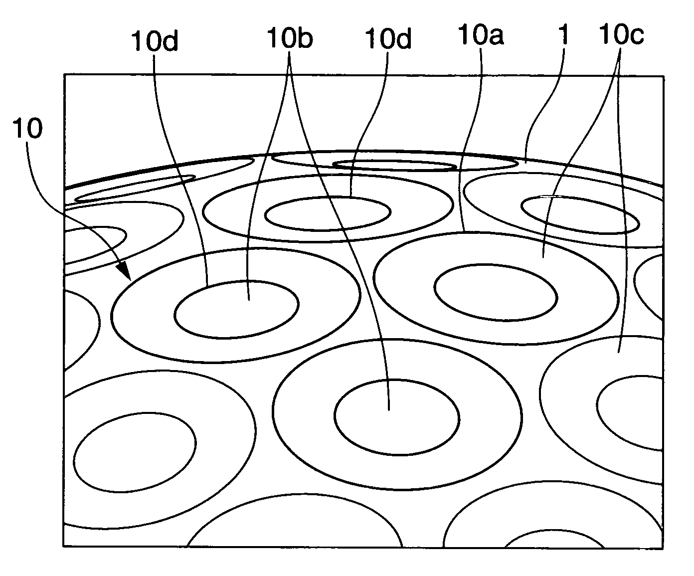
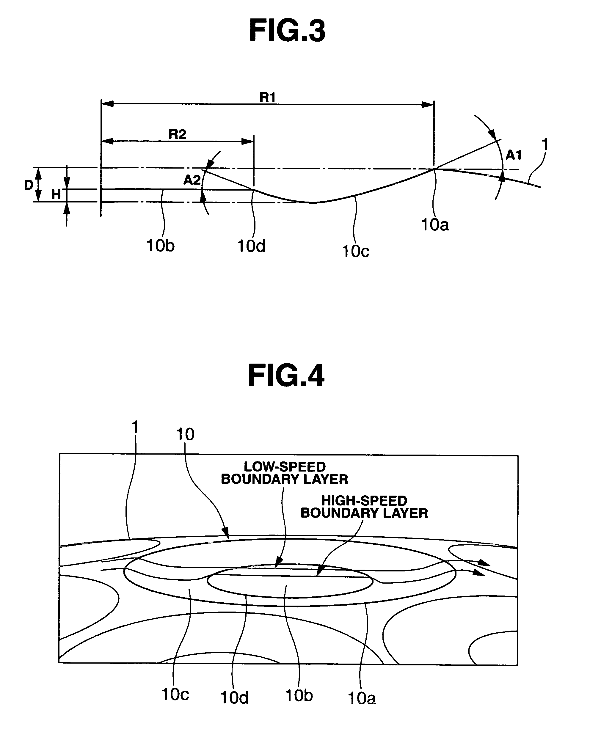
The present invention provides a golf ball with improved aerodynamic performance due to dimple effects. The inventors have designed dimples with a cross-sectional shape that optimizes performance in both the high-speed and low-speed regions of the ball's trajectory. Specifically, the dimples have a raised region with a circular edge and a ring-like wall with a curved cross-sectional shape. The raised region has a flat top face and is at most 60% of the dimple depth. The total number of dimples is at least 250 but not more than 360, with at least one-half being dimples with a diameter of at least 4.2 mm. The raised region has an edge angle of 10 to -30 degrees and the circular outer edge has an edge angle of 10 to -30 degrees. The raised region has a height at most 40% of the dimple depth from the circular outer edge to the deepest position on the ring-like wall.
Problems solved by technology
However, when numerous dimples are formed on the surface of the ball, the stream of air at the surface of the ball during flight changes from laminar flow to turbulent flow, causing the airflow separation point to retreat and lowering the air resistance.
In addition, increasing the lift is known to be a major factor in lengthening the flight time of the ball and thus extending its distance of travel.
However, the dimple designs developed up until now have been limited in the degree to which they extend the distance traveled by a golf ball.
Method used
View moreImage
Smart ImageViewing Examples


Examples
examples
[0037]Examples of the invention are given below by way of illustration, and not by way of limitation.
Login to View More PUM
 Abstract
The invention provides a golf ball having a surface on which are formed a plurality of dimples having a circular outer edge that defines the dimple contour. Each dimple has formed therein, near a portion inside the dimple, a raised region with a circular edge, and also has formed therein, between the circular edge of the raised region and the circular outer edge of the dimple, a ring-like wall having a curved cross-sectional shape. The raised region has a top face which is substantially flat, and a height which is at most 60% of the dimple depth from the circular outer edge to the deepest position on the ring-like wall. In this golf ball, the distance of travel can be increased due to an air resistance-decreasing effect and a lift-maintaining effect.
Description
BACKGROUND OF THE INVENTION[0001]The present invention relates to a golf ball which has numerous dimples formed on the surface thereof, and excellent flight characteristics when hit by any golfer, whether amateur or professional.[0002]The thin layer of air that flows close to the surface of a golf ball in flight after being hit is called the boundary layer. In a ball without dimples, a stream of air that is free of turbulence forms at this boundary layer. However, when numerous dimples are formed on the surface of the ball, the stream of air at the surface of the ball during flight changes from laminar flow to turbulent flow, causing the airflow separation point to retreat and lowering the air resistance.[0003]In addition, increasing the lift is known to be a major factor in lengthening the flight time of the ball and thus extending its distance of travel. Moreover, it is also known that forming relatively large dimples on the surface of the ball has the effect of maintaining the li...
Claims
Login to View More Application Information
Patent Timeline
 Patent Type & Authority Applications(United States)
IPC IPC(8): A63B37/12
CPCA63B37/0004A63B37/0007A63B37/001A63B37/0012A63B37/0017A63B37/0021A63B37/0019A63B37/002A63B37/0022A63B37/0015A63B37/0018
Inventor KASASHIMA, ATSUKISATO, KATSUNORI
Owner BRIDGESTONE SPORTS
Features
- R&D
- Intellectual Property
- Life Sciences
- Materials
- Tech Scout
- Unparalleled Data Quality
- Higher Quality Content
- 60% Fewer Hallucinations
Learn More Browse by: Latest US Patents, China's latest patents, Technical Efficacy Thesaurus, Application Domain, Technology Topic, Popular Technical Reports.
© 2025 PatSnap. All rights reserved.Legal|Privacy policy|Modern Slavery Act Transparency Statement|Sitemap|About US| Contact US: help@patsnap.com