
High Dynamic Range Texture Filtering

a texture filtering and high dynamic range technology, applied in the field of three-dimensional (3d) computer graphics, can solve the problems of high gate count of filtering units, computational cost of bilinear (or trilinear) filtering of floating point texture data, and high computational cost of current graphics hardwar

Inactive Publication Date: 2008-01-03
NOKIA CORP
View PDF4 Cites 22 Cited by
  • Summary
  • Abstract
  • Description
  • Claims
  • Application Information

AI Technical Summary

Benefits of technology

[0007]This Summary is provided to introduce a selection of concepts in a simplified form that are further described below in the Detailed Description. This Summary is not i

Problems solved by technology

However, this can present challenges with current graphics hardware.
Although such hardware often supports floating point computations for textures and pixel shaders, bilinear (or trilinear) filtering of floating point texture data is computationally expensive and requires complex texture filtering units

Method used


Image

  • High Dynamic Range Texture Filtering
  • High Dynamic Range Texture Filtering
  • High Dynamic Range Texture Filtering

Examples


Embodiment Construction

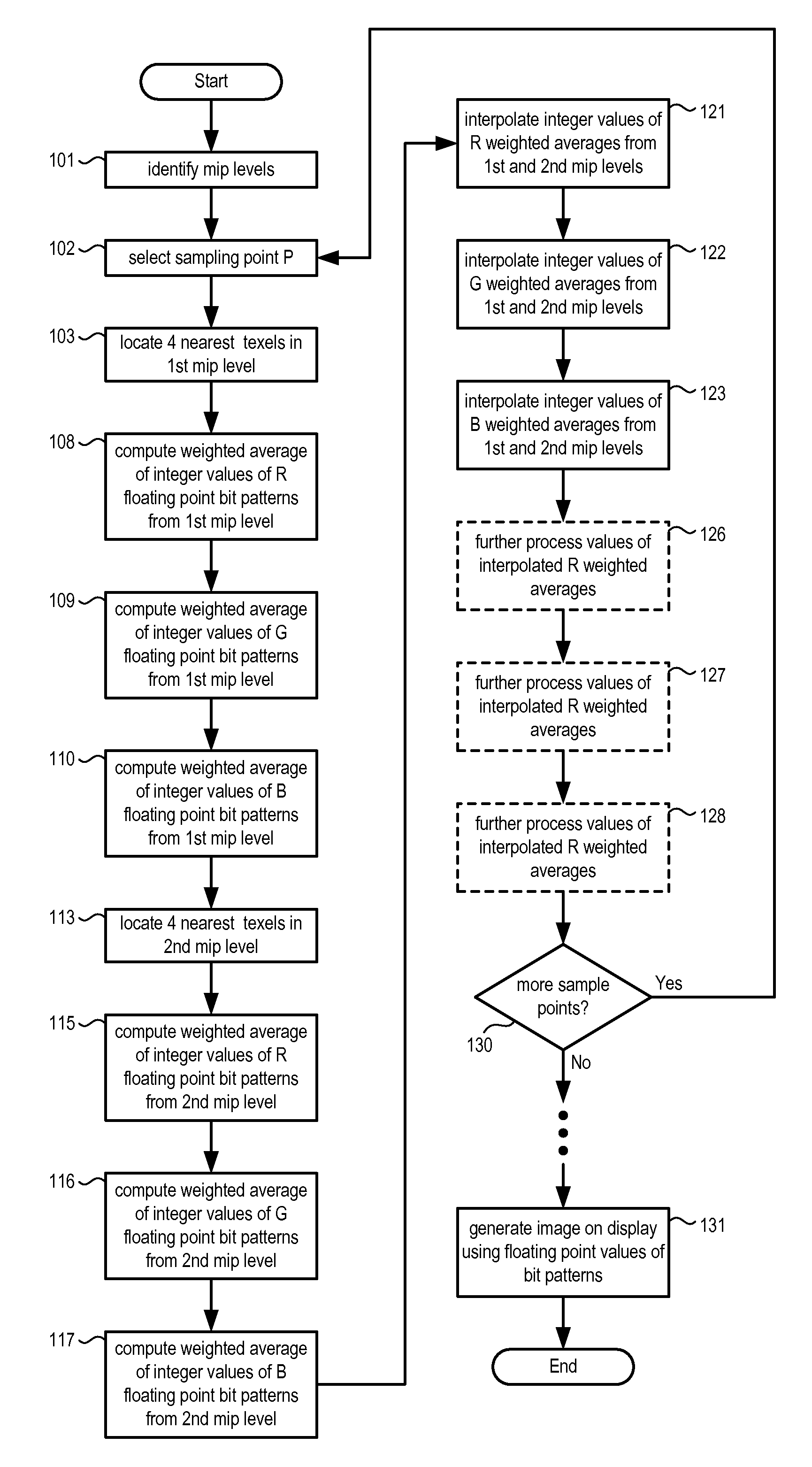
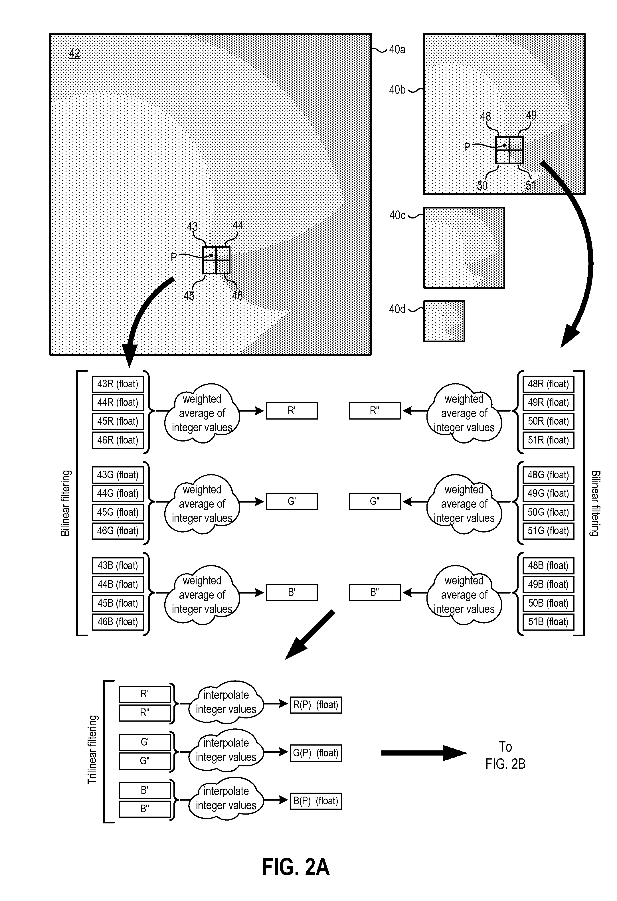
[0018]Embodiments of the invention facilitate processing of graphical data such as high dynamic range (HDR) texture data using simpler hardware than would be required using conventional techniques. As a result, higher quality images can be rendered on a display more quickly. In at least some embodiments, integer bit patterns of floating point data values are filtered. For example, and as described in further detail below, one floating point data format defines the most significant bit of a multi-bit field as a sign bit, a group of the next most significant bits as an exponent, and the least significant bits as a mantissa. When performing a filtering computation using such a multi-bit floating point value, the bits are simply treated as the binary representation of an integer. After filtering operations are performed, the bit patterns of the filtered values are once again treated as floating point values. Although treatment of floating point values as integers is not mathematically e...


PUM


Abstract

Bit patterns storing floating point data values are interpreted as integer values during various graphical data processing operations. For example, when bilinearly filtering color intensity data for bitmap regions closest to a designated sampling point, the bit patterns representing each of those color intensities are interpreted as integers instead of floating point values. Bit patterns can also be treated as integers when trilinearly filtering color intensity data from multiple bitmaps. After processing the bit fields as integers, the results are then interpreted as floating point values.

Description

FIELD OF THE INVENTION[0001]The invention generally relates to three dimensional (3D) computer graphics. In particular, embodiments of the invention relate to devices and methods for performing high dynamic range (HDR) rendering.BACKGROUND OF THE INVENTION[0002]In computer graphics, details are frequently added to surfaces of 3D objects through a technique known as texturing. One or more surfaces of the object to be displayed are first identified. Those surfaces can be regularly shaped (e.g., a wall, a surface of a sphere or of a cube, etc.), irregularly shaped (e.g., a complex surface defined by a table of points), or a combination of regular and irregular shapes. A separate image is then mapped onto the surface. One common example is a wall in a computer game. The wall may be defined as a planar surface positioned at a certain location within the graphical universe of the game. That wall can then be represented as a brick wall by mapping points of a separate brickwork pattern imag...

Claims


Application Information

Patent Timeline
IPC IPC(8): G09G5/00
CPCG06T15/04G06T3/4007
Inventor ROIMELA, KIMMOAARNIO, TOMIITARANTA, JOONAS
Owner NOKIA CORP
Learn More