
Wave-Guide-Notch Antenna

a technology of waveguides and antennas, applied in the direction of antennas, slot antennas, basic electric elements, etc., can solve the problems of increasing complexity, e.g. manufacturing, and the dielectrics are often too heavy to be considered for large array antennas

Active Publication Date: 2007-12-27
TELEFON AB LM ERICSSON (PUBL)
View PDF6 Cites 169 Cited by
  • Summary
  • Abstract
  • Description
  • Claims
  • Application Information

AI Technical Summary

Problems solved by technology

Balanced antenna elements such as the radiating portion of a notch element possesses excellent bandwidth properties, but are cumbersome to realise, e.g. to manufacture.
The situation becomes even more complex when the possibility to switch between different polarisation states (e.g. linear and circular) is required.
However, such dielectrics tend to be far too heavy to be considered for use in large array antennas.
However there are doubts that high performance notch elements can be slot-fed because of seemingly disparate transverse field distributions.
However, a split interface in a protruding ridge / notch region of the antenna element implies boundary conditions not implemented in EM analysis software of today.
Standard ridged wave-guide feeds do not easily fit into standard lowcost industrial manufacturing methods, while probe or stripline fed slots do, as doses a probe fed ridge.
However these documents are considered to only constitute the state of the art and in any way not anticipating the present application.

Method used


Image

  • Wave-Guide-Notch Antenna
  • Wave-Guide-Notch Antenna
  • Wave-Guide-Notch Antenna

Examples


Embodiment Construction

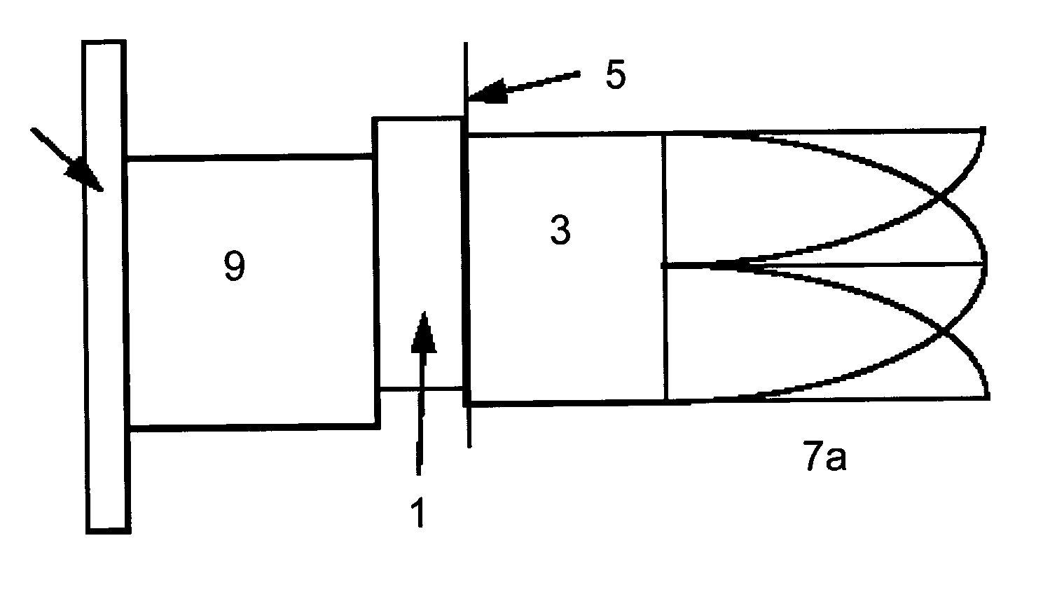
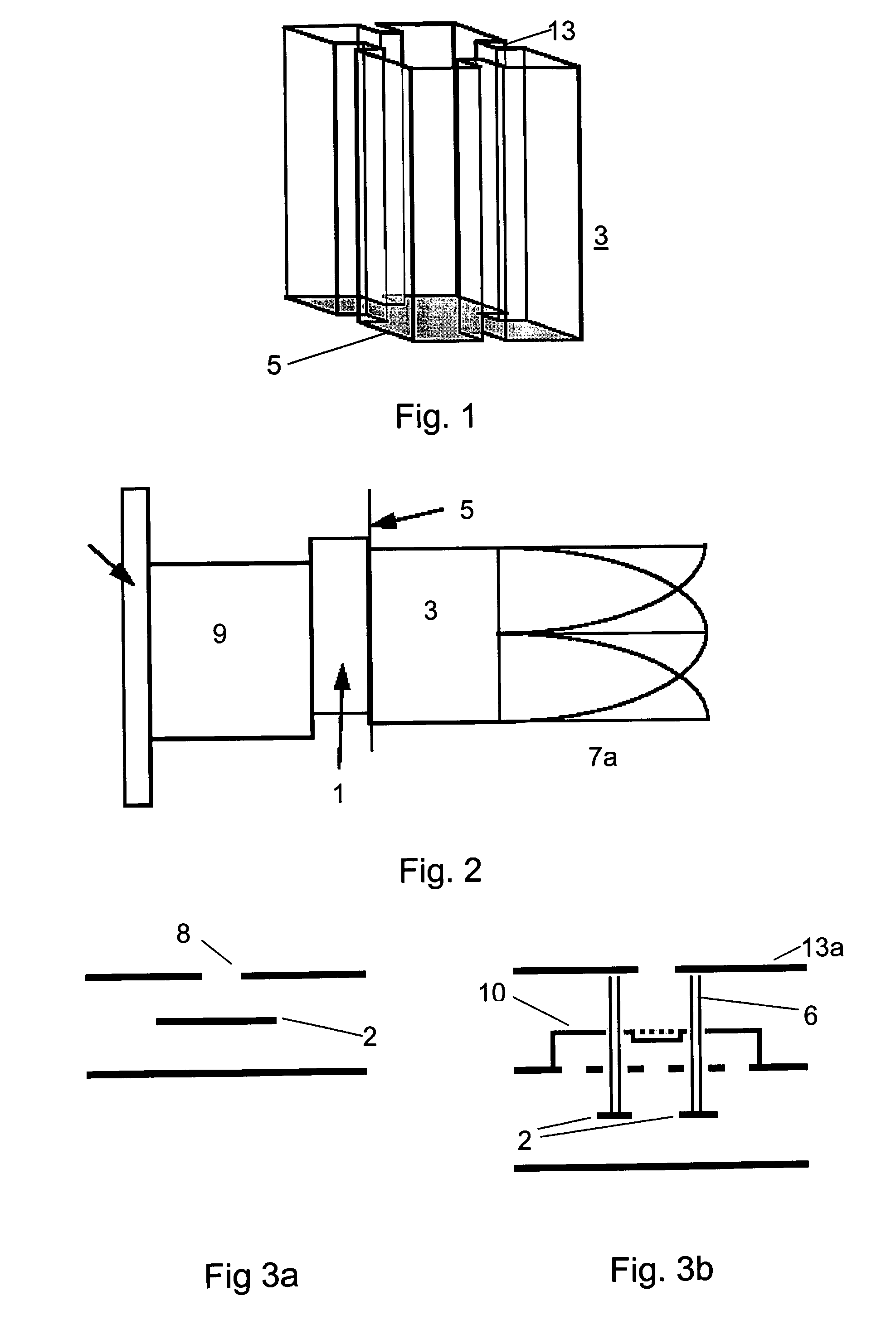
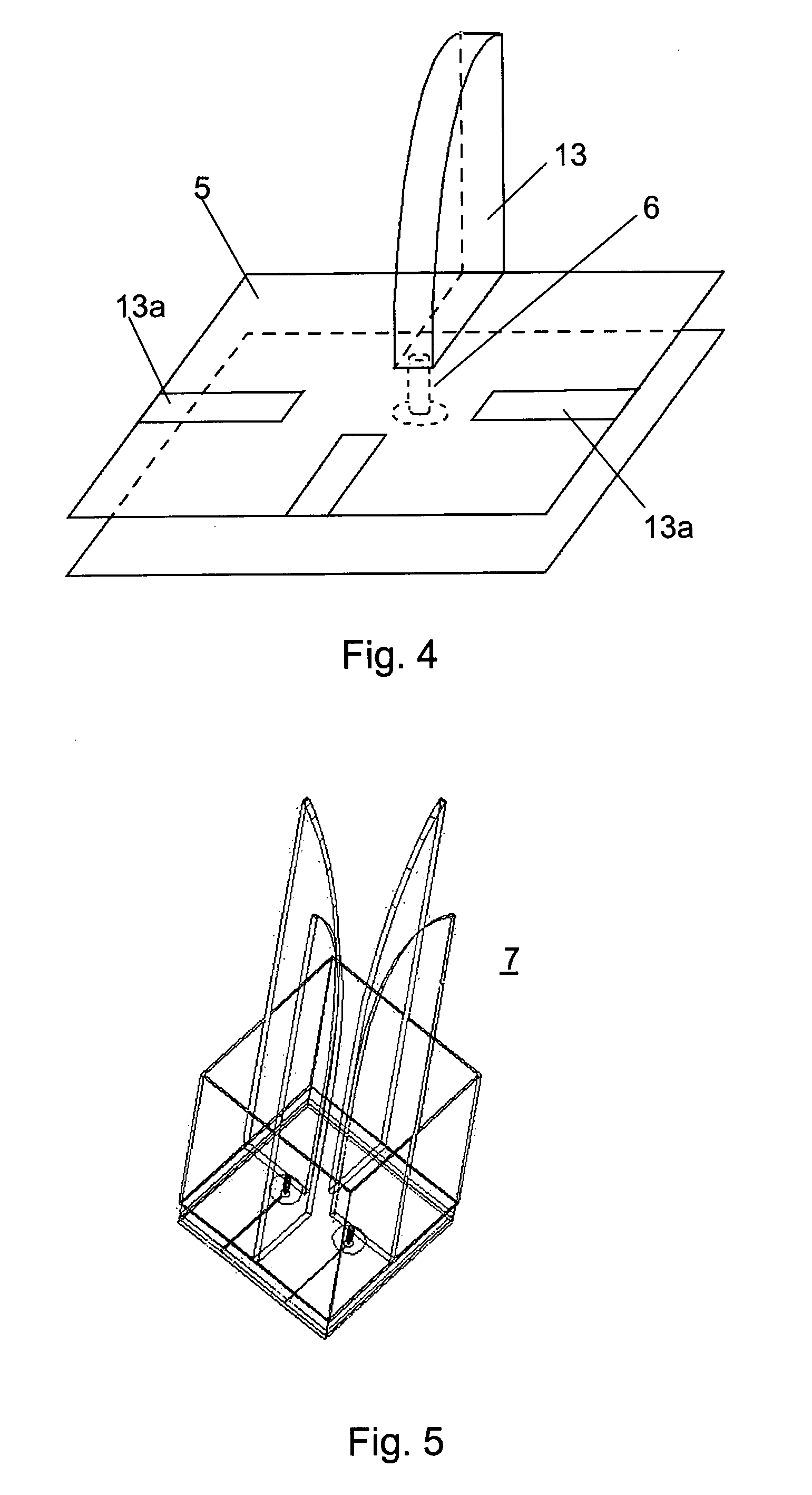
[0027] An embodiment of the invention consists of a feed section 1 constituting a strip-line section or a probe section, where two (or more) input transmission lines 2 and / or probes 6 are arranged so that e.g. one linear and one circular polarisation is transmitted (or received) depending on how the input transmission lines 2 are excited. The feed section 1 transfers the strip-line wave or the probe wave to a wave-guide mode (and vice versa), of a ridged wave-guide section 3, a feed / wave-guide interface, e.g. in the form of crossed slots. The wave-guide mode finally enters the tapered notch section 7, which due to its TEM character gradually adjusts the field towards free-space conditions (Z0≈377 ohms) outside the antenna. (Also see FIG. 2, FIG. 3a and FIG. 3b).

[0028] Thus, a feed section 1 may consist of a strip-line section with at least one hybrid feeding the crossed-slot feed / wave-guide interface aperture. In another embodiment the feed section is realised using longitudinal pr...


PUM


Abstract

A dual polarised wave-guide notch antenna array is disclosed. The device comprises a feed section (1) having at least two input transmission lines, a feed / wave-guide interface (5) providing an aperture for transferring a radio frequency electromagnetic wave between the feed section (1) and a wave-guide mode in a wave-guide section (3) having ridges. The wave-guide section transfers energy between the feed / wave-guide interface and a tapered notch section (7), thereby gradually adjusting a created electromagnetic field towards free space conditions.

Description

TECHNICAL FIELD [0001] The present invention relates to a wave-guide-notch antenna and more particularly a dually polarised wave-guide-notch antenna. BACKGROUND [0002] When designing electrically steerable antennas (ESA) one strives for at least some of the following properties: low-weight, broad-band, dual polarisation, low losses, wide coverage, adequate packaging and a construction simple to manufacture as well as at low cost. [0003] Balanced antenna elements such as the radiating portion of a notch element possesses excellent bandwidth properties, but are cumbersome to realise, e.g. to manufacture. One reason for this is that at least one transmission line per element needs to cross the ground plane, implying a feed through and possibly a contact. [0004] The situation becomes even more complex when the possibility to switch between different polarisation states (e.g. linear and circular) is required. [0005] A convenient way of feeding antenna elements above a ground plane is exc...

Claims


Application Information

Patent Timeline
Patent Type & Authority Applications(United States)
IPC IPC(8): H01Q13/10
CPCH01Q13/0241H01Q13/085H01Q13/0275
Inventor HOOK, ANDERSWESTERBERG, JESSICAJOHANSSON, JOAKIM
Owner TELEFON AB LM ERICSSON (PUBL)
Learn More