Septic system
a technology of septic system and septic tank, which is applied in the field of septic system, can solve the problems of large septic system not fitting on the desired building lot, deficient operation of septic system, etc., and achieve the effect of improving interface and improving interfa
- Summary
- Abstract
- Description
- Claims
- Application Information
AI Technical Summary
Benefits of technology
Problems solved by technology
Method used
Image
Examples
second embodiment
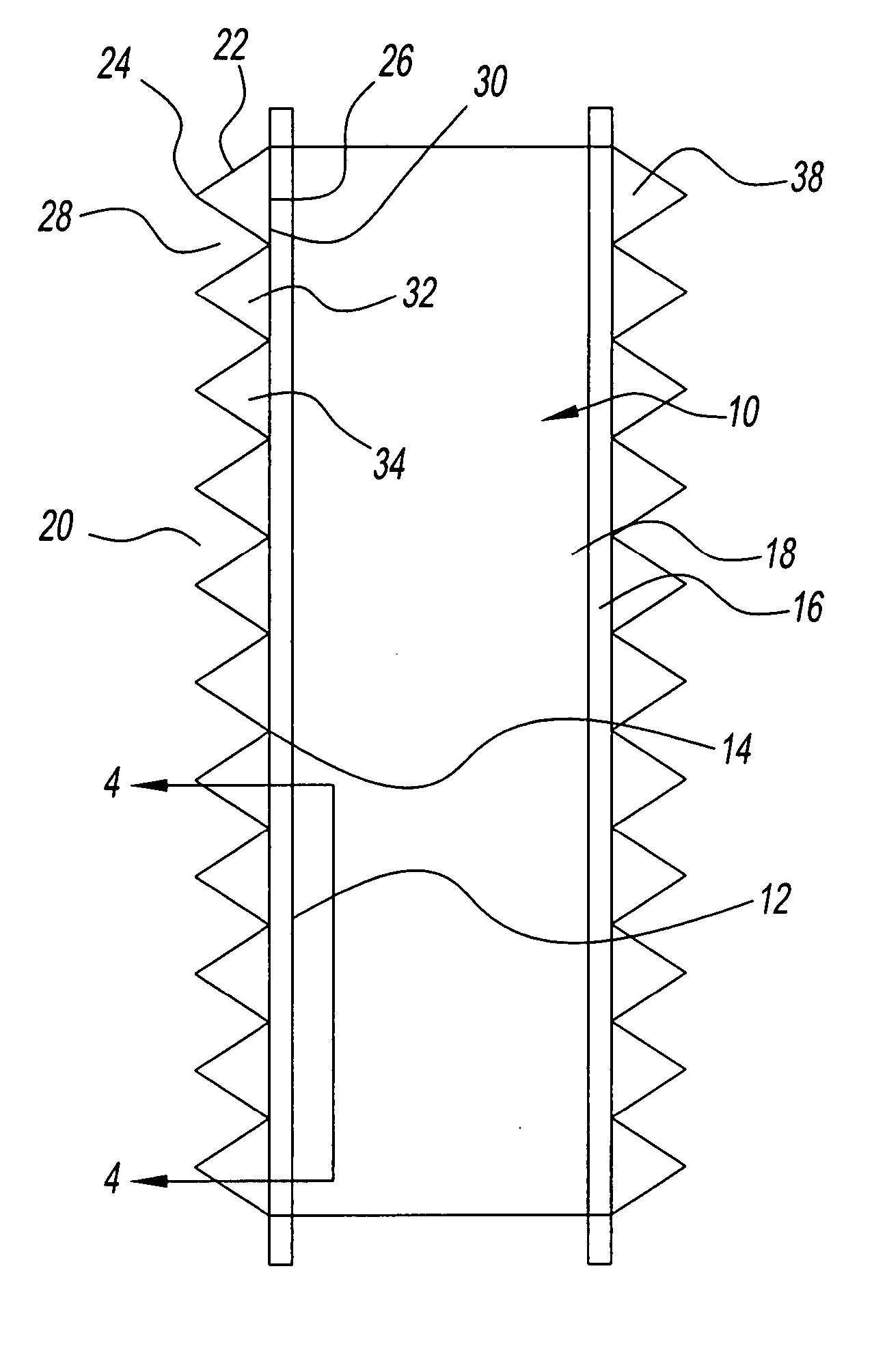
[0052] Referring to FIGS. 5 and 6, an appendage system 40 of the present invention, is shown. System 40 has two appendages 42 and 44 that are abutting each other. Each appendage 42 and 44 can have any number of triangular elements 46 to form a baffle 48. Each baffle 48 has numerous apertures 54 to allow for passage of effluent into leaching field. Triangular elements 46 can have rounded tips 50 to further increase the surface area of diffusion of liquid into the soil 52 in the leaching field. Baffle 48 preferably increases a surface area of the lateral side of the first appendage 42 and 44 to allow an increased amount of liquid effluent to escape from the appendages and channel 56, and traverse through the apertures and for diffusion to the sand, or ground.
third embodiment
[0053] In the present invention shown in FIGS. 7 and 8, septic system 80 has an entirely unitary structure. System 80 has a first baffle 85 and a second baffle 90. Each baffle has a plurality of trapezoidal appendages 95 and 100, respectively, integrally connected thereto to form a unitary trapezoidal configuration. A center channel 105 or conduit extends through the center of baffle 85 and facilitates the flow of effluent from source and through appendages 95 and 100. Channel 105 has a relatively small diameter relative to the dimensions of the appendages 95, to maintain a small footprint of the entire system without compromising dispersion capability. Channel 105 has a length of approximately from 6 feet to approximately 8 feet long. The height and width are approximately 1 foot to 4 feet depending upon the required capacity of the system. Appendages 95 and 100 are approximately 1 feet to 3 feet in length away from channel 105. The overall with of conduit 105 together with appenda...
fourth embodiment
[0054] In an fourth embodiment, a septic system 110 is shown in FIGS. 9 and 10. Septic system 110 also has a plurality of appendages 115 that each have a flattened tip to form a polygon such as a trapezoid, instead of an apex as shown in the previous embodiment. The plurality of trapezoidal shaped appendages 115 collectively form a baffle 120. Appendages 115 are on opposite sides of gallery 125 to effect the diffusion of effluent. Appendages 115 each have a pattern of holes 130 therethrough to expedite the passage of the effluent into the surrounding soil. In addition to a pattern of holes 130 extending through the appendages surfaces 135, surface 135 also have a plurality of protuberances 140 thereon. Protuberances 140 maintain a distance between the appendage faces 135 and any filter material placed over appendages faces 135. The protuberances 140 extend in a direction perpendicular to the surface of the appendage surfaces 135. The dimensions of protuberances 140 vary from 0.25 in...
PUM
 Abstract
Description
Claims
Application Information
 - R&D
- Intellectual Property
- Life Sciences
- Materials
- Tech Scout
- Unparalleled Data Quality
- Higher Quality Content
- 60% Fewer Hallucinations
Browse by: Latest US Patents, China's latest patents, Technical Efficacy Thesaurus, Application Domain, Technology Topic, Popular Technical Reports.
© 2025 PatSnap. All rights reserved.Legal|Privacy policy|Modern Slavery Act Transparency Statement|Sitemap|About US| Contact US: help@patsnap.com


