
Optical pickup

a technology of optical discs and pickups, applied in the field of optical pickups, can solve problems such as possible adverse effects in recording/reading and achieve the effect of accurately recording or reading information on optical discs

Inactive Publication Date: 2007-11-29
HITACHI MEDIA ELECTORONICS CO LTD
View PDF5 Cites 3 Cited by
  • Summary
  • Abstract
  • Description
  • Claims
  • Application Information

AI Technical Summary

Benefits of technology

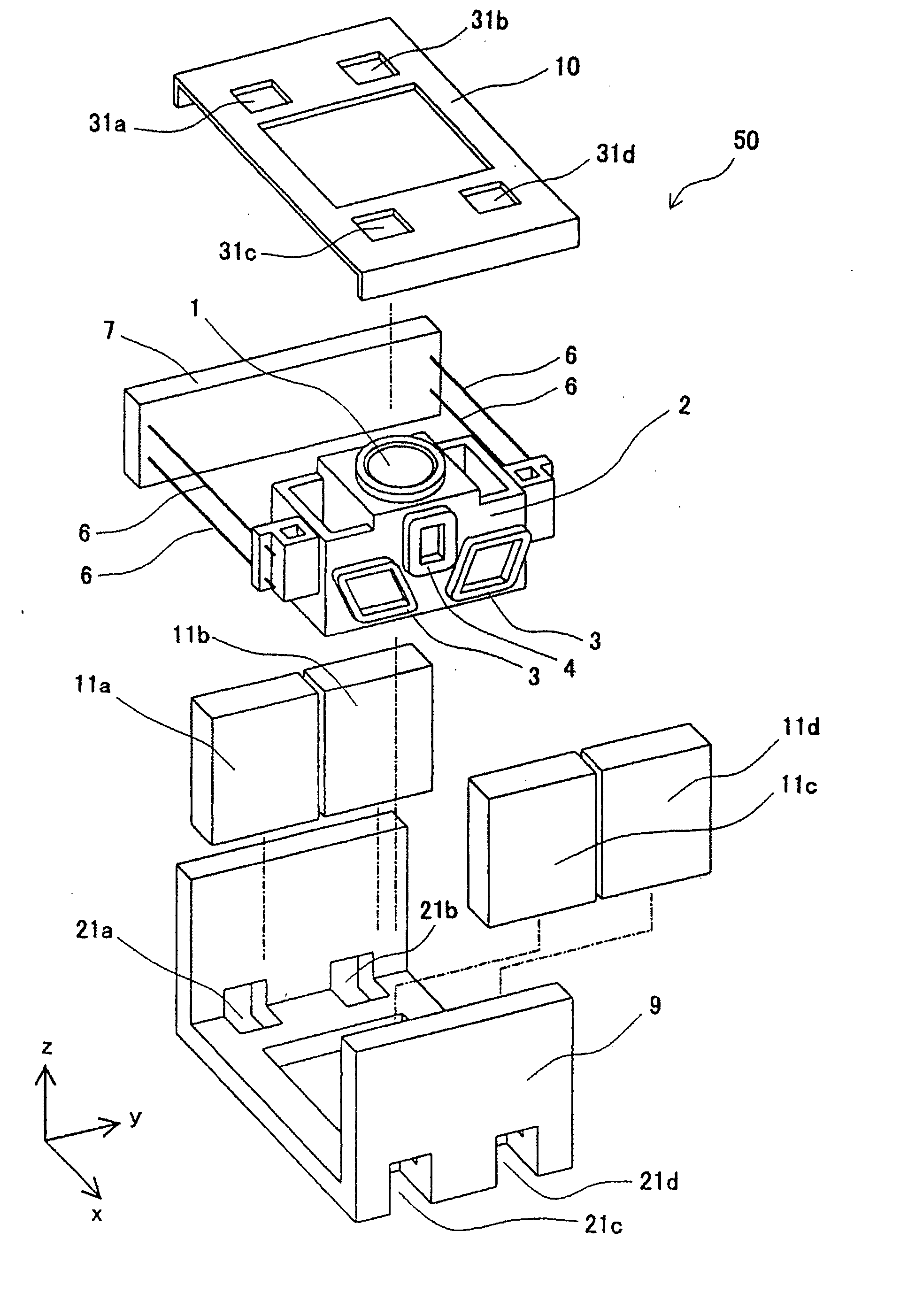
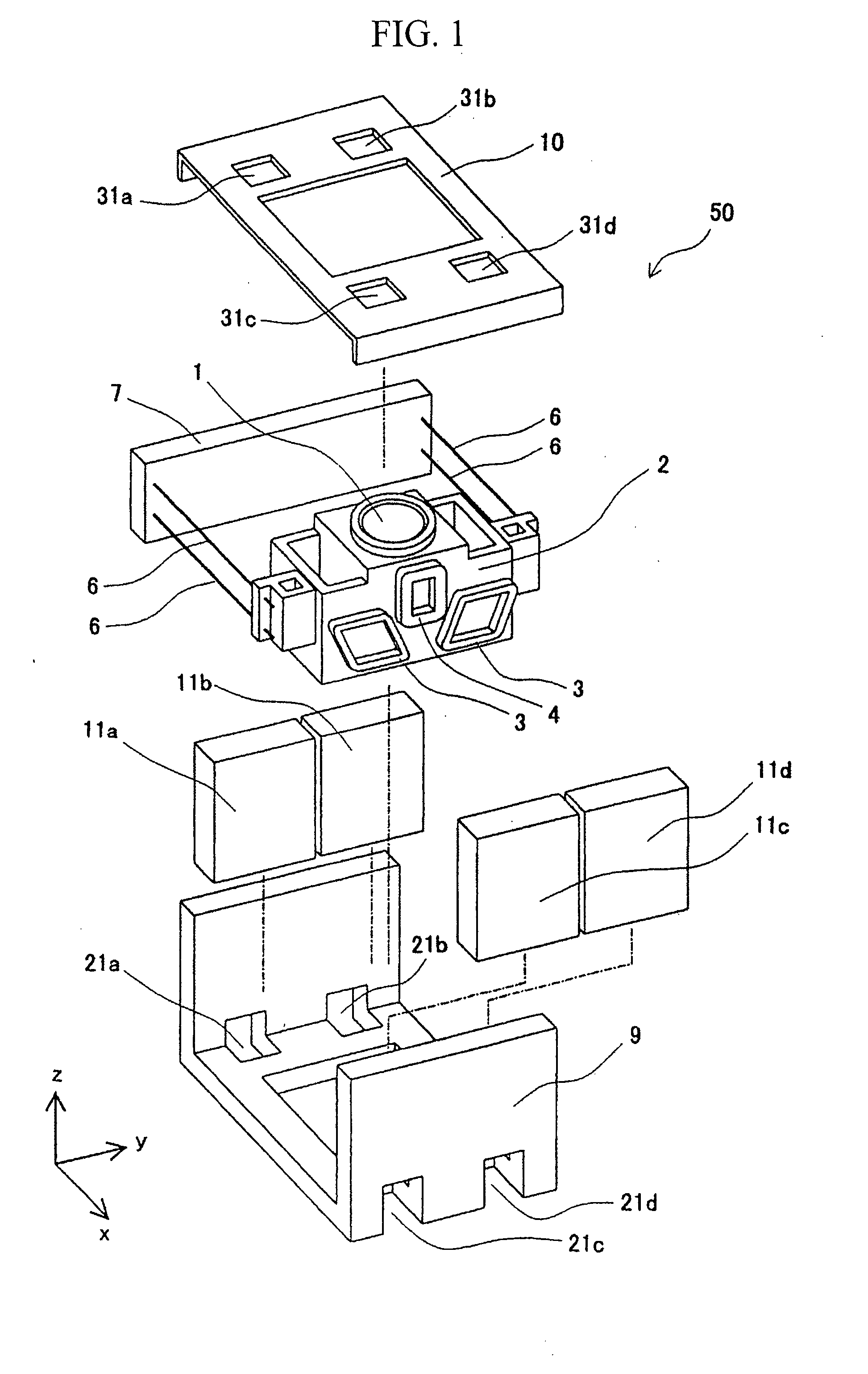
[0009]In accordance with the present invention, jigs that sandwich the magnet are inserted through the openings of the yoke and the cover disposed near the top and bottom of the magnet, and thus, the position of the magnet can be adjusted along the optical axis of the objective lens, depending on the inclination of the moving part with respect to the magnet. Thus, since the moment generated by the coils upon movement of the moving part can be reduced, it is possible to provide an optical pickup having an objective lens with small inclination and to accurately record or read information on an optical disc.

Problems solved by technology

However, in cases in which inclination of the objective lens is caused when the moving part is moved in the focusing or tracking direction, optical aberration is generated, resulting in a possible adverse effect in recording / reading information on the optical disc.

Method used


Image

  • Optical pickup
  • Optical pickup
  • Optical pickup

Examples


embodiment 1

[0018]An embodiment of the optical pickup according to the invention will be described with reference to the drawings.

[0019]Initially, an optical disc drive 100 in which an optical pickup 110 is mounted is described with respect to a block diagram of FIG. 8. The optical disc drive 100 comprises a spindle motor 120 for rotating an optical disc 101, an optical pickup 110 for reading or writing information on the optical disc 101, and a controller 130 for controlling these components. The optical pickup 110 comprises an objective lens driving means 50, of which the details will be described later, and optical components such as a laser light emitting device 111.

[0020]A disc rotation control circuit 131, which is connected to the controller 130, receives an instruction therefrom and drives the spindle motor 120 on which the optical disc 101 is mounted. A feed control circuit 132, which is also connected to the controller 130, receives an instruction therefrom and causes the optical pick...


PUM

PropertyMeasurementUnit
magnetic fluxaaaaaaaaaa
electromagnetic forceaaaaaaaaaa
driving forceaaaaaaaaaa

Abstract

An optical pickup in which the position of a magnet can be adjusted with respect to a yoke is provided. The optical pickup has an objective lens, a lens holder that holds the objective lens, a magnet disposed opposite to a side surface of the lens holder, and a yoke to the inside of which the magnet is attached. The yoke has an opening at least near the bottom of the magnet, through which the magnet can be visually observed from the outside of the yoke, the bottom being on the side of the yoke that is farther from an optical disc and the top being on the side of the yoke that is closer to the optical disc along the optical axis of the objective lens.

Description

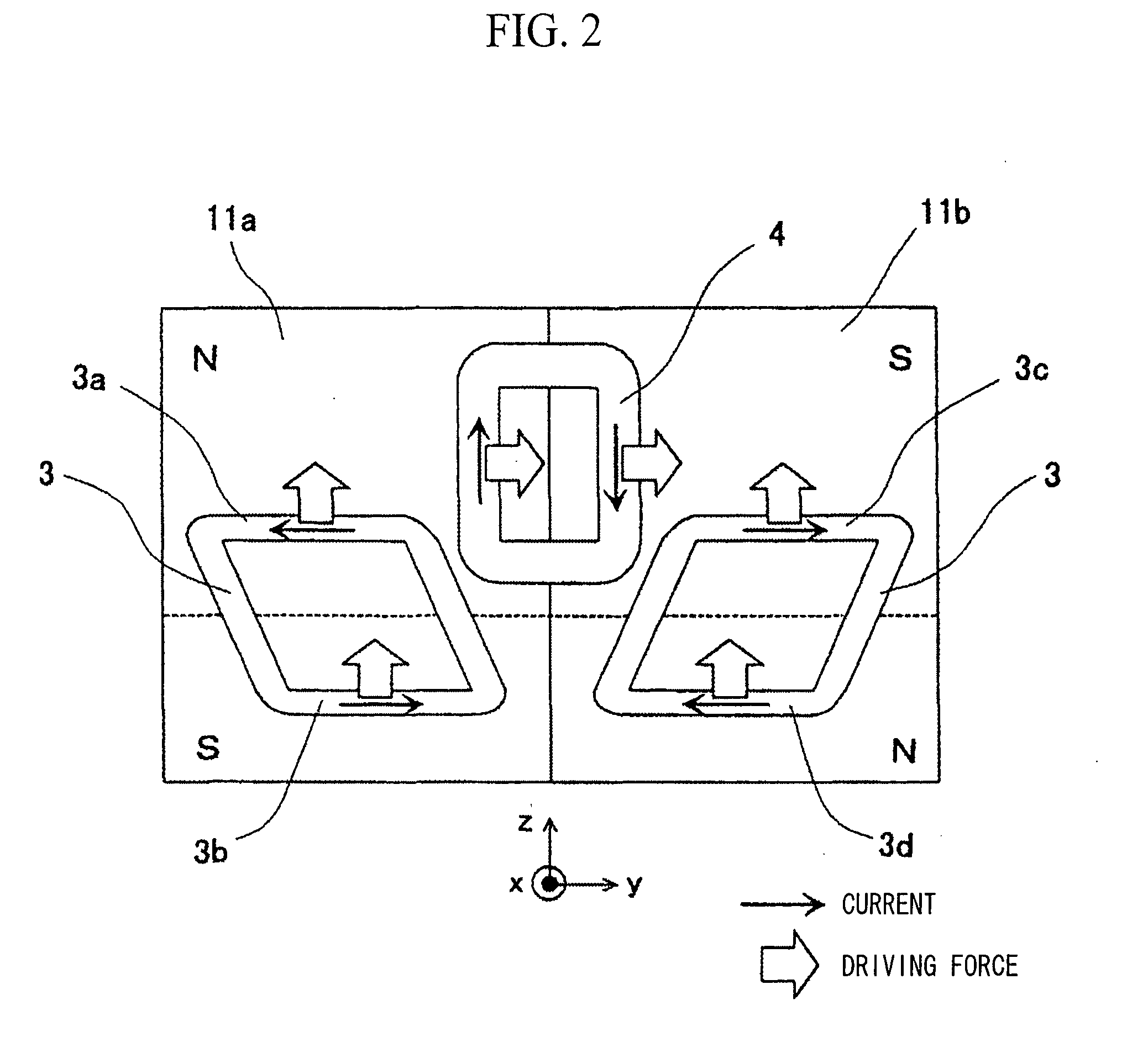
FIELD OF THE INVENTION[0001]The present invention relates to an optical pickup provided in optical disc drives for reading information recorded on a recording surface of an optical disc or for recording information thereon.BACKGROUND ART[0002]A conventional objective lens driving means provided in the optical pickup of an optical disc drive is composed of a moving part on which an objective lens is mounted, supporting members for supporting the moving part, focusing coils, tracking coils, a yoke, and magnets.[0003]When a drive current is applied to the focusing coils, electromagnetic force is produced by the interaction of the current with the magnetic flux developed by the magnets. The electromagnetic force drives the moving part in the focusing direction, which is either toward or away from the optical disc surface. Similarly, when a drive current is applied to the tracking coils, electromagnetic force is produced by the interaction of the current with the magnetic flux from the m...

Claims


Application Information

Patent Timeline
Patent Type & Authority Applications(United States)
IPC IPC(8): G11B7/00G11B7/1381
CPCG11B7/0935G11B7/0933
Inventor KIMURA, KATSUHIKOSAITO, HIDENAOHATO, JUNYAMAGUCHI, TAKAHIRO
Owner HITACHI MEDIA ELECTORONICS CO LTD
Learn More