
Firearm accessory mount adapted for use with rifles having tangent or ladder-style read sights

a technology for accessory mounts and rifles, applied in the field of accessory mounts, can solve the problems of not providing precision, sights that cannot be mounted on the receiver of an assault style rifle, and not working well on aftermarket mounts, etc., and achieve the effect of higher spring coefficien

Inactive Publication Date: 2007-11-29
KENG
View PDF16 Cites 57 Cited by
  • Summary
  • Abstract
  • Description
  • Claims
  • Application Information

AI Technical Summary

Benefits of technology

[0018] An important advantage of the present invention is that the accessory mount does not permanently alter the firearm in any way. It is just a simple matter of exchanging the standard rear sight lever arm for the protuberance portion of the accessory mount. If a user has second thoughts, he or she can go back and change it out the other way, since installation doesn't harm the firearm in any way.

Problems solved by technology

The tangent sights on all of these rifles, while crudely effective, do not provide the precision now sought by many sportsmen who have recently acquired these rifles, and many users now seek a simple and effective way to mount telescopic sights and other types of optical sighting aids.
Modern optical sights include the AimPoint™ and the EO-Tech™ red dot sights, and such sights do not work well when mounted upon an assault style rifle's receiver.
Others have attempted to make aftermarket mounts available, but with limited success.
In general, the releasable mounts or replacement receivers with attached scope mounts (e.g., a Weaver or picatinny rail) are not very stable and are not precise enough to guarantee that a the point of aim or “zero” will be restored once the user disassembles the firearm for cleaning.
At the end of the shooter's day, to clean the gun one must take the gun apart and there is no way to do that without removing the receiver cover first, at which point the zero is lost, since upon re-installation, the point of aim will have changed.
The problem with mounting either dovetails or mounting plates on the left side of the AK receiver is that it alters the weapon permanently and technical issues often foil unskilled people trying to mount these types of plates.
One can mount the plate in the wrong place and actually block internal moving parts, interfering with the insertion of the magazine.
Such changes also permanently destroy a rifle's collector value.
Others use picatinny rails manufactured right into forearms to replace the standard forearms and when mounting an optic there, the optic is too far forward to see a correct sight picture.
The more serious problem, though, is that it gets very hot near the forearm very quickly, since the forearm is directly over the gas tube on an AK, and an unwary user can overheat and damage an optical sight.
Another problem confronting the shooter on a limited budget is that the AK and its variants often were manufactured using stamped steel receivers, and so were not suited to conventional scope rail mounts, which are usually affixed by threaded fasteners after drilling and tapping a rifle's receiver.

Method used


Image

  • Firearm accessory mount adapted for use with rifles having tangent or ladder-style read sights
  • Firearm accessory mount adapted for use with rifles having tangent or ladder-style read sights
  • Firearm accessory mount adapted for use with rifles having tangent or ladder-style read sights

Examples


Embodiment Construction

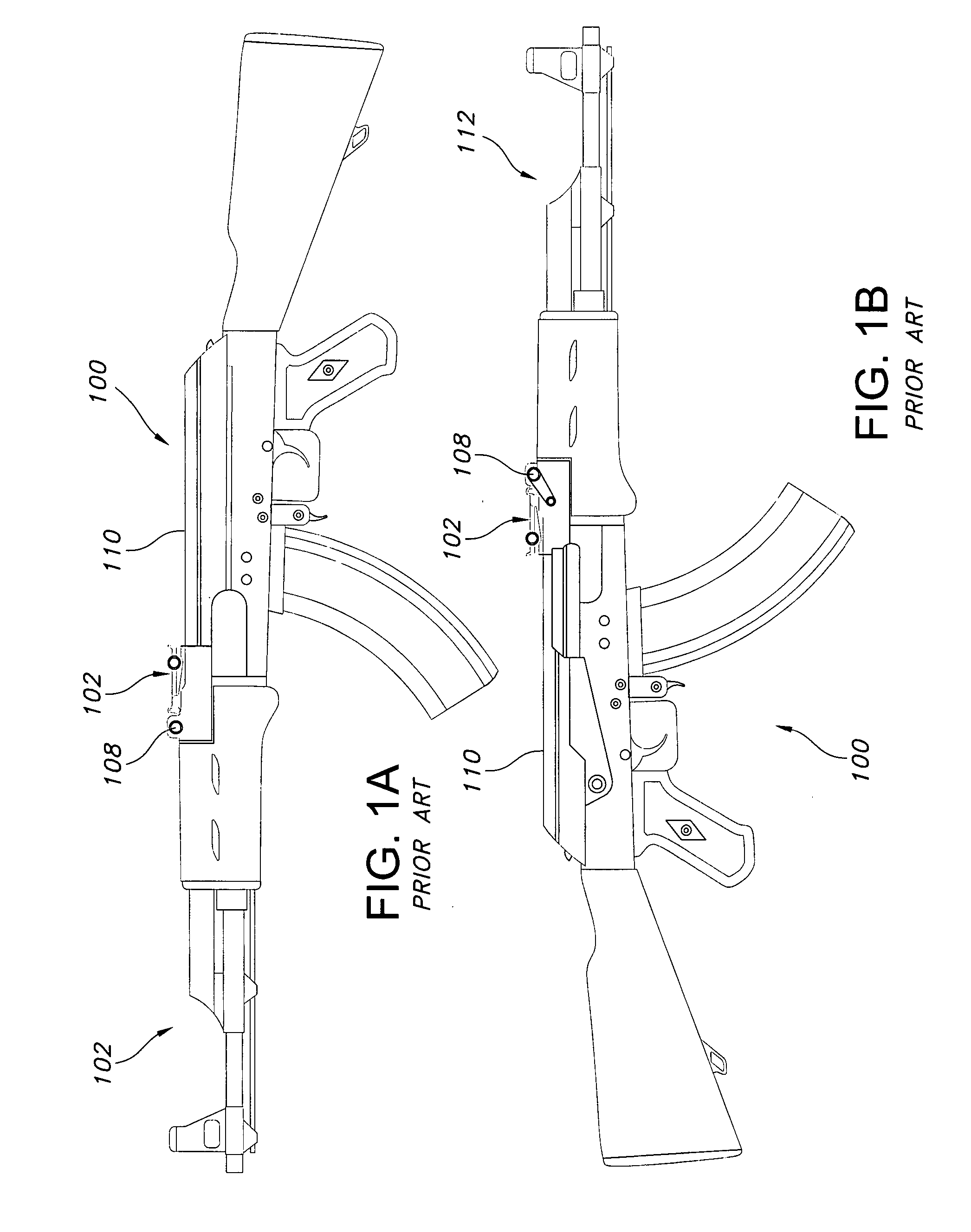
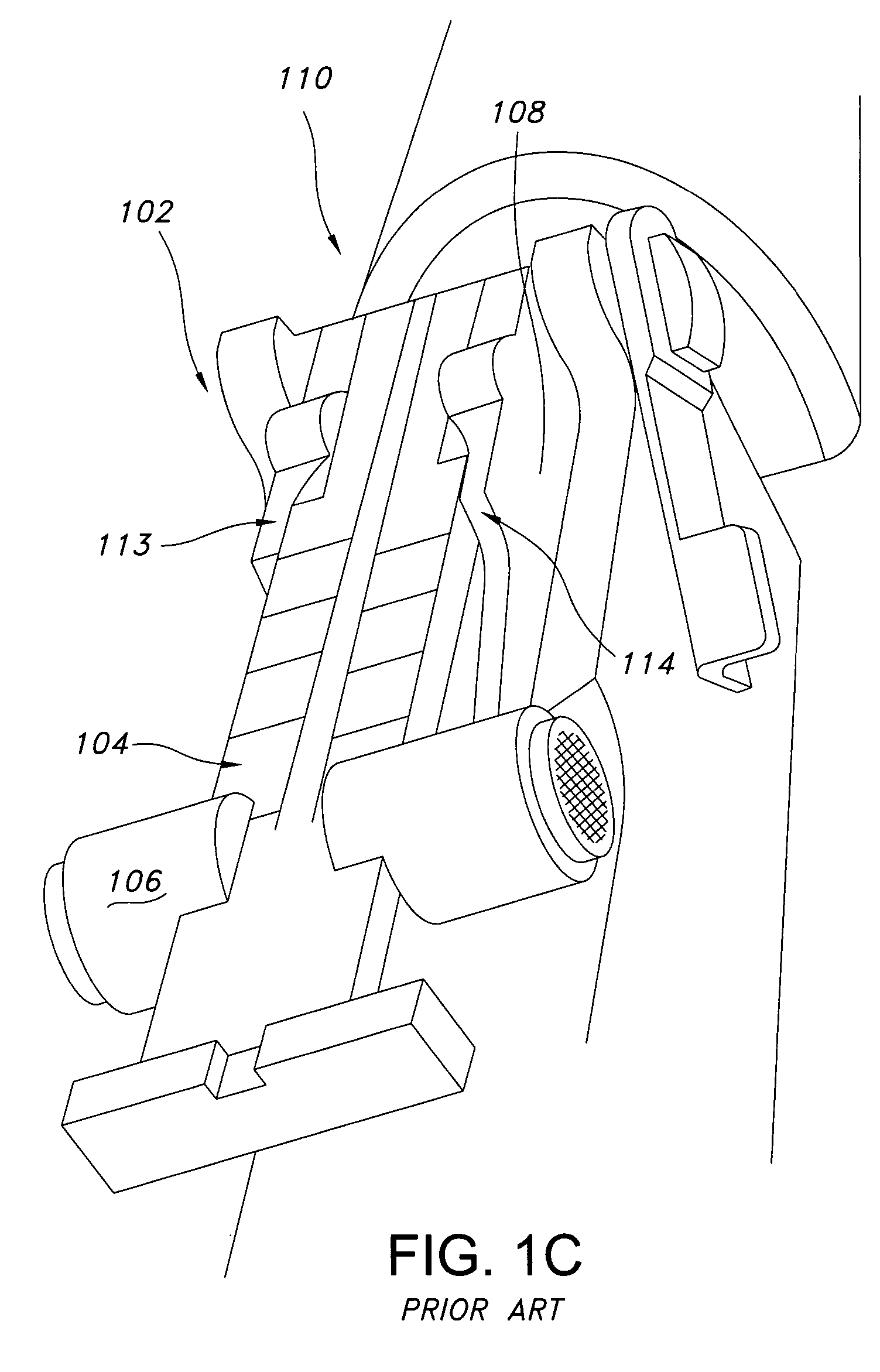
[0034] Referring now to FIGS. 1-8, FIGS. 1a and 1b show a standard AK-47 rifle 100, and illustrate the position of the standard tangent rear sight assembly 102 including a pivoting elongated leaf member 104 carrying a slide 106. As shown in FIG. 1c, Tangent rear sight assembly 102 includes a sight base 108 solidly mounted over the distal end of the rifle's receiver 110, above the barrel 112. As best seen in FIG. 1d, the standard sight base 108 has left and right spaced apart side walls 113, 114 terminating distally in left and right opposing trunnion or pin receiving segments 116 and 118. The open central portion 111 of sight base 108 includes a powerful biasing leaf spring 120 which biases upwardly to stabilize and retain the opposing pins or trunnions of elongate rear sight leaf member 104, when installed. All of the forgoing is well known to gunsmiths and armorers around the world who build, repair and maintain the millions of AK-47 style rifles in use today.

[0035]FIGS. 2-8 illu...


PUM


Abstract

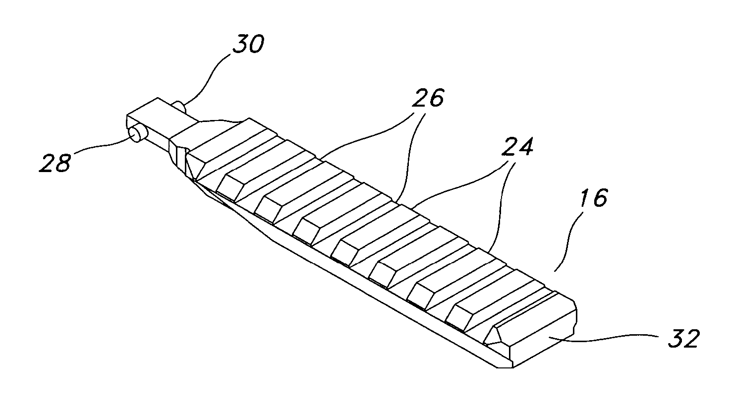
An accessory mount is removably affixed in place of a pre-existing tangent rear sight lever arm or leaf. The accessory mount is adapted for installation by a user without gunsmithing and includes an elongated body with a distal protuberance carrying opposing transverse trunnions or pins adapted to engage the tangent sight's base. In a preferred embodiment of the present invention, the elongated body has an upper surface configured to accept accessories designed to clamp on a Picatinny-style rail, or a Weaver™ style rail and so provides a universal mounting surface for optical sights, scope rings or other accessories.

Description

CROSS-REFERENCE TO RELATED APPLICATIONS [0001] This application claims priority, under 35 U.S.C. 119(e), to U.S. Provisional Application No. 60 / 771,019 filed Feb. 8, 2006, the entire contents of which are incorporated herein by reference.BACKGROUND OF THE INVENTION [0002] 1. Field of the Invention [0003] The present invention relates to firearms and accessory mounts for securing accessories, such as optical sights, to firearms. [0004] 2. Description of Related Art [0005] Soviet and Eastern-Bloc firearm designs have become widely available to the public, and purchasers of rifles often want to use optical sights or other firearm accessories that are not readily mounted on rifles patterned after those designs. [0006] To name one example, the AK-47 (Avtomat Kalashnikova 1947) is a gas-operated assault rifle designed by Mikhail Kalashnikov, produced by Russian manufacturers, and used in many Eastern bloc nations during the Cold War. It was adopted and standardized in 1947. It was one of ...

Claims


Application Information

Patent Timeline
IPC IPC(8): F41G1/387
CPCF41G11/003F41G1/387
Inventor KENG, DA
Owner KENG
Learn More