
Catheter assembly with tip shield closure

a catheter and closure technology, applied in the field of catheter assemblies, can solve the problems of blood leakage or splashing out of the opening on the downside of the compartment, and achieve the effect of reducing the risk of leakage or splashing of blood

Active Publication Date: 2007-11-22
BECTON DICKINSON & CO
View PDF12 Cites 99 Cited by
  • Summary
  • Abstract
  • Description
  • Claims
  • Application Information

AI Technical Summary

Benefits of technology

The present invention is a covering for a catheter assembly that prevents blood from leaking or splashing out of the tip shield. It includes a resilient clip compartment that can fill with blood during use. The covering blocks an opening in the compartment to prevent any leakage or splashing. This invention reduces the risk of complications during catheter use.

Problems solved by technology

The blood may leak or splash out of an opening on the downside of the compartment.

Method used


Image

  • Catheter assembly with tip shield closure
  • Catheter assembly with tip shield closure
  • Catheter assembly with tip shield closure

Examples


Embodiment Construction

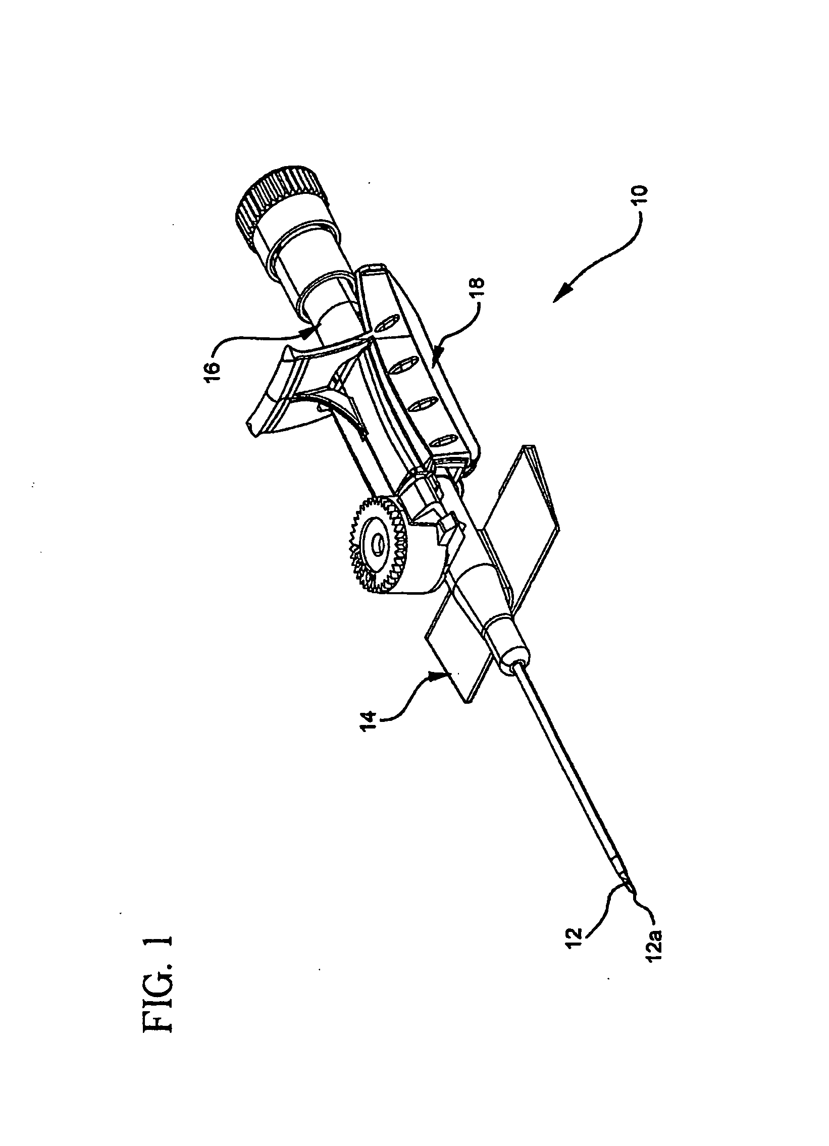
[0022]FIG. 1 is a representative embodiment of catheter assembly 10 prior to placement in a vessel. Catheter assembly 10 includes needle 12 with needle tip 12a, catheter hub 14 and needle hub 16 with grip portion 18. The distal end of catheter assembly 10 is generally toward needle tip 12a and the proximal end is generally toward needle hub 16. Lateral regions are situated at or extending toward the sides of catheter assembly 10. Medial regions are at or toward the midline of catheter assembly 10, with the midline running in a longitudinal direction.

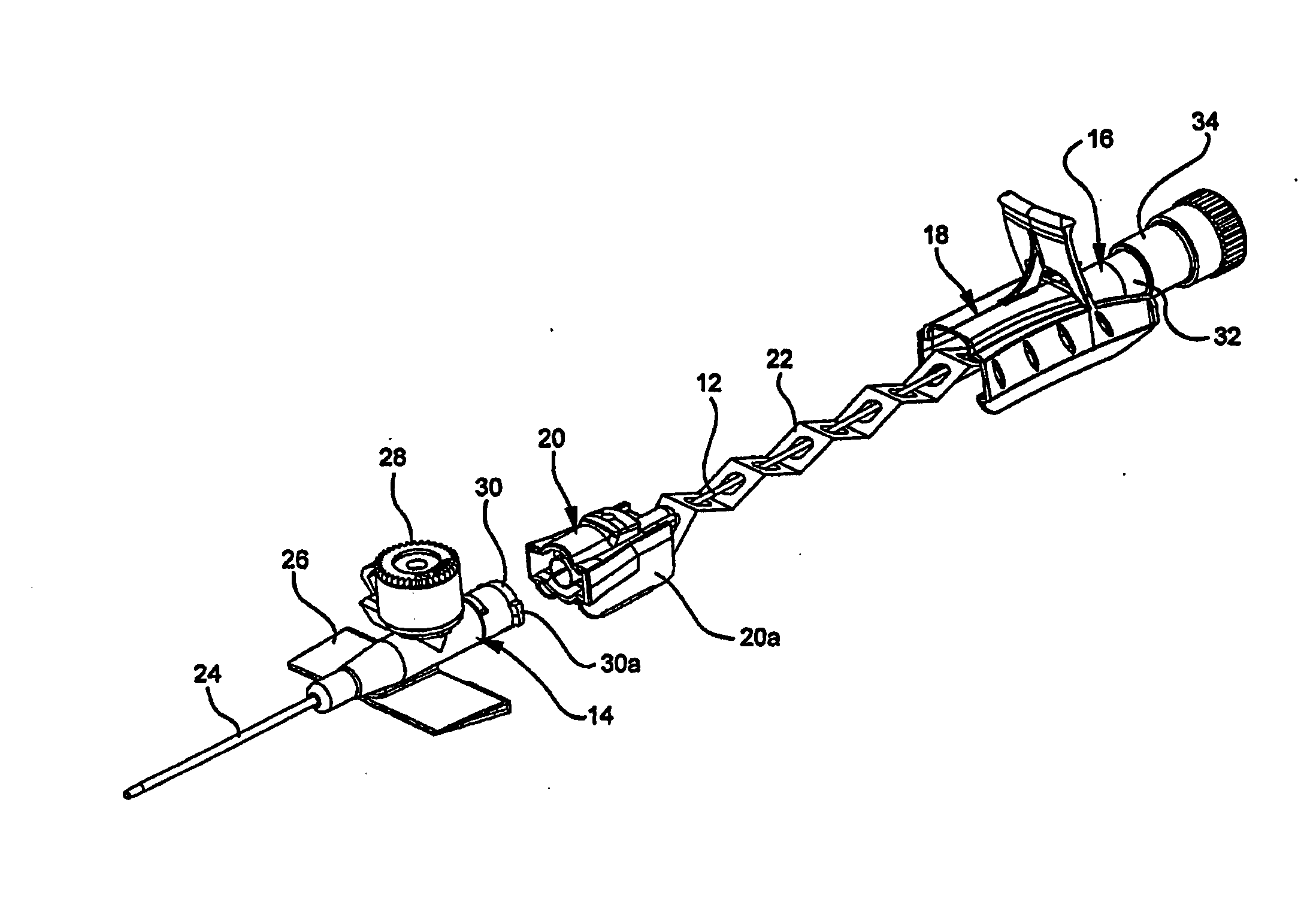
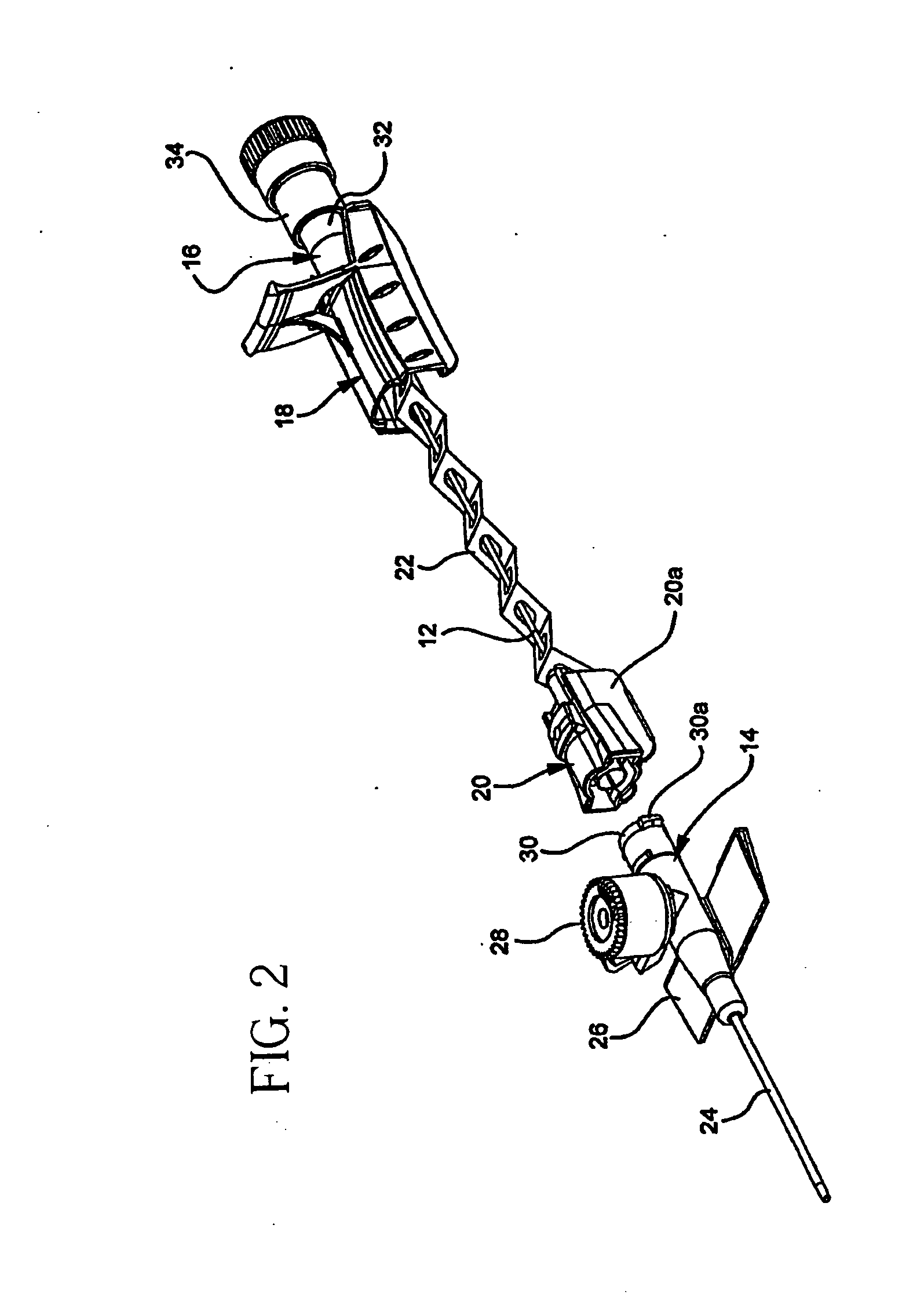
[0023]FIG. 2 shows catheter assembly 10 after placement into a vessel. In addition to the elements shown in FIG. 1, FIG. 2 includes tip shield 20 with housing 20a and tether 22. Catheter hub 14 includes catheter 24, wings 26, injection port 28 and notch 30 with luer lock member 30a. Needle hub 16 includes flashback chamber 32 and flow control plug 34.

[0024] In use, needle 12 of the assembled catheter assembly 10 shown in FIG. 1 is inse...


PUM


Abstract

A tip shield of a catheter assembly has a resilient clip compartment, which may become blood-filled during use of the catheter assembly. The resilient clip inside the compartment is released upon withdrawal of the needle of the catheter assembly to disengage the catheter hub from the tip shield. The resilient clip also prevents re-exposure of the needle after being withdrawn into the tip shield. The blood-filled compartment may potentially leak or splash through an opening from the compartment when the resilient clip is released. A covering blocks the opening from the tip shield to minimize the risk of blood exposure. In addition, the covering minimizes the risk of premature release of the resilient clip and re-exposure of the needle.

Description

[0001] This application is related to an application entitled IV CATHETER ASSEMBLY WITH AN ERGONOMIC NEEDLE GRIP, which was filed on the same day and also assigned to Becton, Dickinson and Company.BACKGROUND OF THE INVENTION [0002] The present invention relates to a catheter assembly. In particular, the present invention relates to a tip shield for a catheter assembly. [0003] Intravascular catheters are used for infusing fluid into a patient, withdrawing fluid from a patient, or monitoring various parameters of the patient's vascular system. Typically, a needle is used to introduce the catheter into a patient's blood vessel. A catheter is mounted over a needle that has a sharp distal tip with at least the distal portion of the catheter tightly engaging the outer surface of the needle to prevent peel-back of the catheter during insertion into the blood vessel. [0004] A clinician inserts the catheter and needle through the patient's skin and into the patient's blood vessel. Once a fla...

Claims


Application Information

Patent Timeline
Patent Type & Authority Applications(United States)
IPC IPC(8): A61M5/00A61M5/178A61M5/32
CPCA61M5/3275A61M2005/325A61M25/0637A61M25/0625
Inventor SODERHOLM, KARL JOHAN MARTENLUNDQVIST, JANNE JOAKIMHAGER, JORGEN BRUNOLARSSON, LARS-AKE LENNARTGLOWACKI, KRISTOFFER
Owner BECTON DICKINSON & CO
Learn More