
Swept-frequency measurements with improved speed using synthetic instruments

a technology of synthetic instruments and swept frequency, applied in instruments, testing/monitoring control systems, cathode-ray oscilloscopes, etc., can solve the problems of adding considerable complexity to the system, difficult or impractical approach, and inability to use swept frequency measurement modes

Active Publication Date: 2007-11-08
KEYSIGHT TECH
View PDF13 Cites 49 Cited by
  • Summary
  • Abstract
  • Description
  • Claims
  • Application Information

AI Technical Summary

Benefits of technology

The patent describes a system for measuring the frequency of a signal. The system includes multiple devices, each with its own clock. These devices communicate with a device under test (DUT) and with a synchronization device that ensures that each device's clock is synchronized. The devices collect measurements of the signal's frequency, which are then synchronized by the synchronization device. The technical effect of this system is that it allows for accurate and synchronized measurements of signal frequency, even in complex systems with multiple devices.

Problems solved by technology

There are typically no timing difficulties associated with this approach and it is the one most often chosen for synthetic test systems, even though these types of synthetic test system measurements have additional overhead associated with them.
Unfortunately, this swept-frequency measurement mode has traditionally not been available to synthetic instruments.
In a synthetic instrument, however, this approach is difficult or impractical to implement and may add considerable complexity to the system because synthetic instrument test systems typically include multiple, independent, non-integrated instruments.
As a result, direct hardware synchronization between these instruments is difficult and more complex than in traditional integrated instruments.
While an integrated spectrum analyzer may synchronize its internal operations utilizing internal hardware signals, and thus achieve highly accurate swept-frequency measurements, this accuracy is more difficult to achieve using synthetic test instruments, due to their lack of synchronization.
However, there will be a difference in the overhead associated with executing the frequency change and subsequent data collection, because the spectrum analyzer utilizes internal hardware signaling to coordinate the two processes, while the synthetic analyzer does not.
In typical implementations, this leads to slower “stepped” mode measurements as each instrument in the synthetic analyzer is stepped to a new frequency and a measurement is performed.
While “swept” mode measurements are possible utilizing synthetic instruments, without the sweep synchronization, they are capable of achieving sufficient accuracy only at greatly reduced sweep rates, making them of questionable value.

Method used


Image

  • Swept-frequency measurements with improved speed using synthetic instruments
  • Swept-frequency measurements with improved speed using synthetic instruments
  • Swept-frequency measurements with improved speed using synthetic instruments

Examples


Embodiment Construction

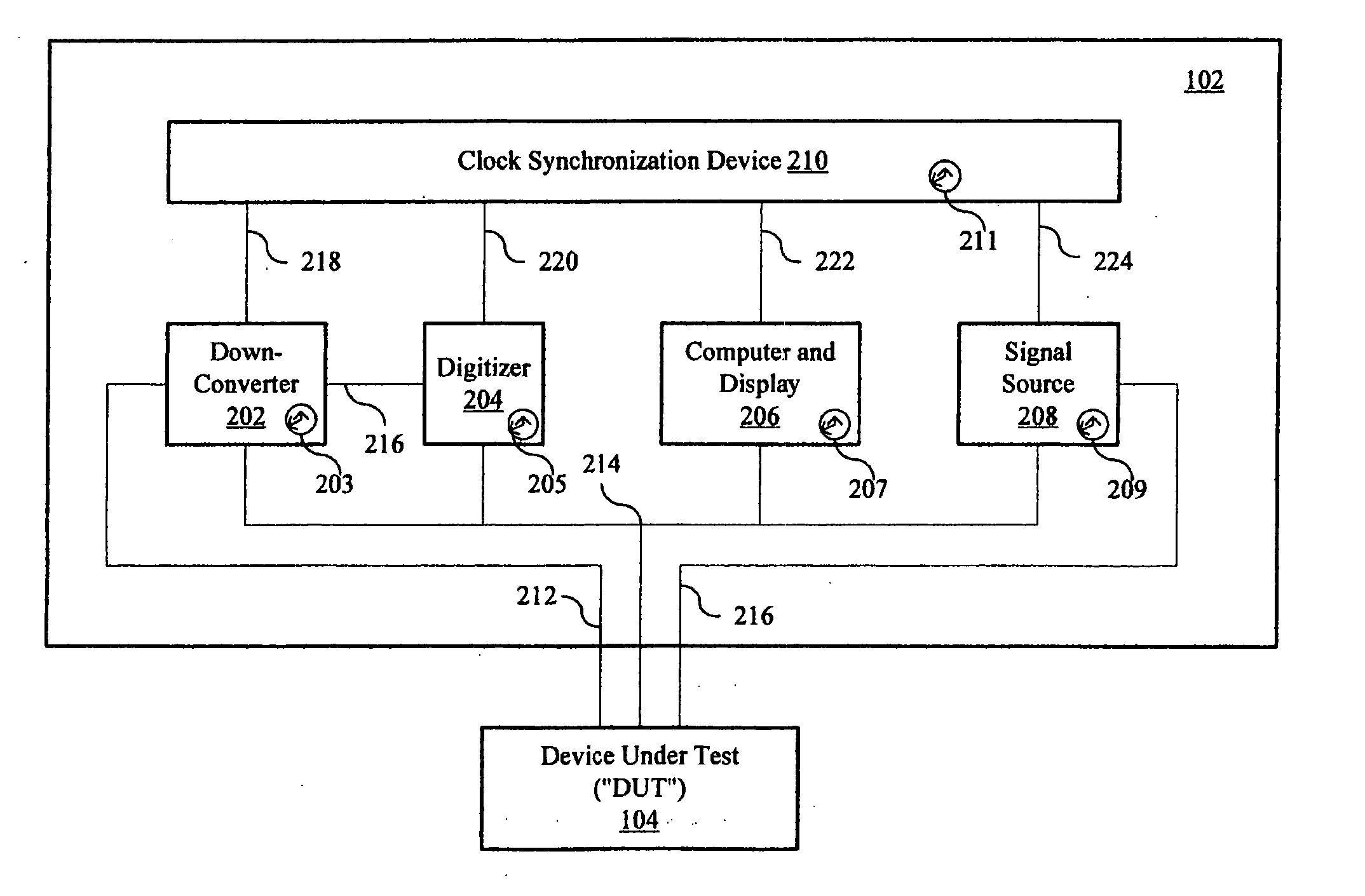
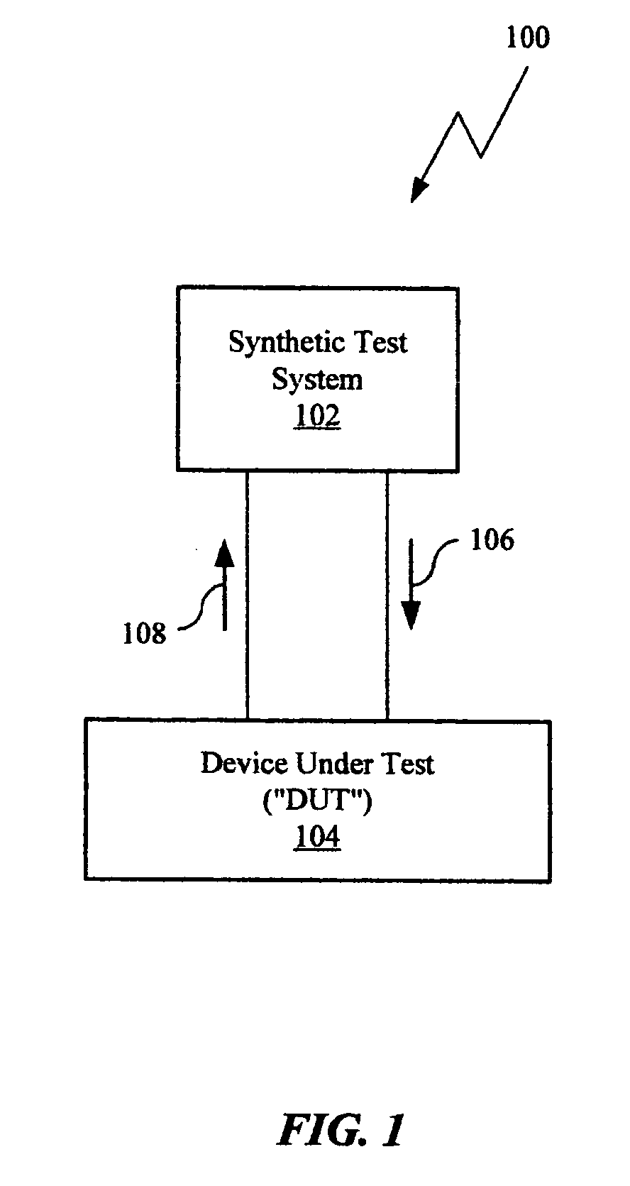
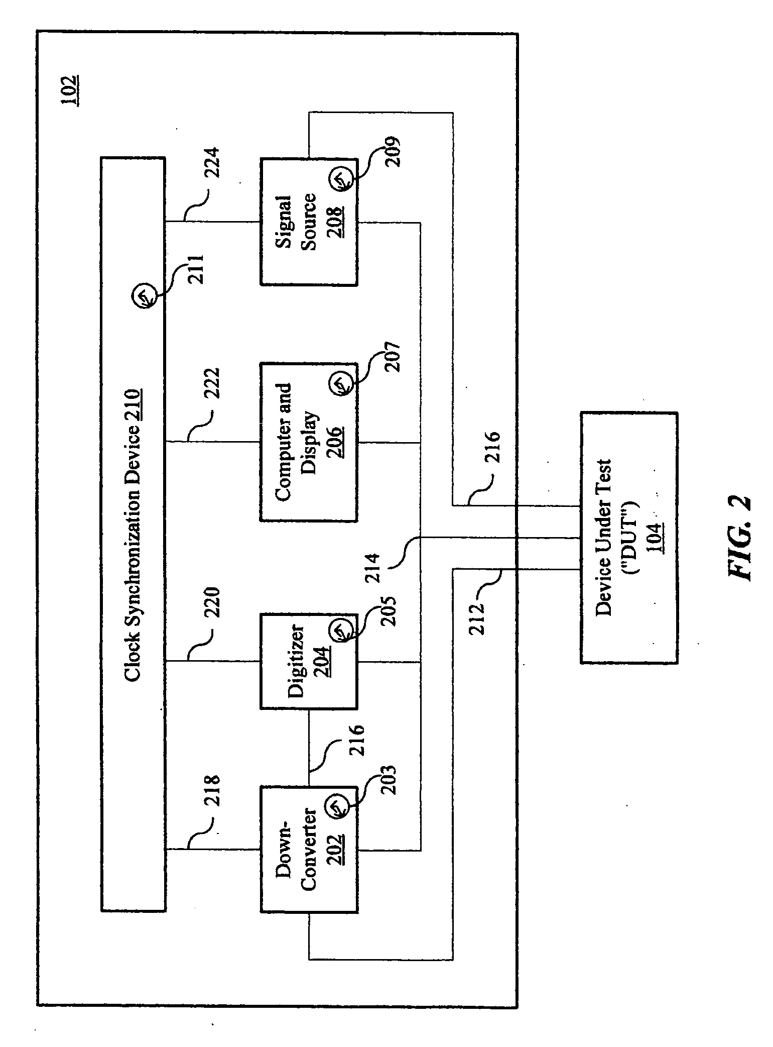
[0016] An approach for highly synchronized swept-frequency measurements is described. In FIG. 1, a block diagram 100 of an example of a synchronized synthetic test system 102 for conducting swept-frequency measurements is shown. The synthetic test system 102 may include a number of test modules that reside in independent test boxes (or test devices) or may have test modules combined in two or more test boxes or (test devices). The test devices in the synthetic test system may be in signal communication with a device under test (“DUT”) 104. Typically there may be at least one signal path for injecting a signal and another signal path for obtaining measurements from the DUT. However, it is appreciated by those skilled in the art that in some test systems it is possible for the DUT 104 to generate a signal without injecting a signal from the synthetic test system 102. Returning to the example shown in FIG. 1, a signal 106 may be injected into the DUT 104 and measurements 108 may be obt...


PUM


Abstract

A synthetic test system for swept-frequency measurements that has a clock synchronization device to enable test boxes and devices that form the synthetic test system to have a common sense of time when conducting swept-frequency tests.

Description

BACKGROUND OF THE INVENTION [0001] It is often necessary and desirable to measure the signals contained within a large frequency range via a swept-frequency measurement of electrical components and circuits to identify faults, verify performance, and determine characteristics of electrical components and circuits that may be referred to as a device under test (“DUT”). An example of a swept-frequency measurement is a spur search measurement, which is often listed among the tests that take the most time to execute. Examples of electrical components and circuits that often require swept-frequency measurements may include amplifiers, transmitters, modulators, and receivers, to name but a few examples. [0002] Swept-frequency measurements typically involve a test device or synthetic test system tuning the local oscillator (“LO”) in a down-converter (or an up-converter, depending on the application) during the execution of the swept-frequency test. In either case, there are typically three...

Claims


Application Information

Patent Timeline
Patent Type & Authority Applications(United States)
IPC IPC(8): G01R23/00G05B23/02G01R13/24
CPCG01R23/16
Inventor PLEASANT, DANIEL LEEWOOD, DUAINE C.GORIN, JOSEPH M.
Owner KEYSIGHT TECH
Learn More