Container with plant identification tag slot

a plant identification and container technology, applied in the field of containers with plant identification tag slots, can solve the problems of difficult use of slits, identification problems, and difficulty in knowing what type of plants are in the containers,

Inactive Publication Date: 2007-11-08
LANDMARK PLASTIC
View PDF16 Cites 9 Cited by
  • Summary
  • Abstract
  • Description
  • Claims
  • Application Information

AI Technical Summary

Benefits of technology

[0012] An additional embodiment A second embodiment of the present invention overcomes at least one disadvantage of the prior art by providing a process for manufacturing a plant container comprising the steps of providing a heated thermal forming mold comprising a vacuum, the mold having a forming shape comprising a frustoconical sidewall having a draft angle and a first circumference at an upper edge of the sidewall, a bottom, a lip positioned near the top of the forming shape, a nesting step between the lip and the sidewall, the nesting step extending around less than all of the first circumference of the sidewall, and wherein the side of the nesting step has a draft angle in the opposite direction of the sidewall draft angle; providing a sheet of thermoplastic material; heating the sheet of material to a temperature higher than the material's glass transition temperature; placing the heated sheet over the mold cavity; using the vacuum to draw the sheet against the mold surface; cooling the sheet of material; ejecting the formed container from the mold; providing a first die set comprising at least one punch and a corresponding die; using the first die set to punch a slot through the lip, the slot positioned where the nesting step is absent; providing a second die set comprising a shearing die; and using the second die set to trim the lip from the sheet.
[0013] A third embodiment of the present invention overcomes at least one disadvantage of the prior art by providing a plant container comprising a frustoconical sidewall having a draft angle and a first circumference at an upper edge of the sidewall; a bottom comprising one or more apertures; a lip positioned near the top of the container; a first nesting step between the lip and the sidewall, the nesting step extending around less than all of the first circumference of the sidewall; a second nesting step between the lip and the sidewall; a slot through the lip, the slot positioned where the first nesting step is absent; wherein the side of the second nesting step has a draft angle approximately the same as the sidewall draft angle, and wherein the side of the first nesting step has a draft angle in the opposite direction of the sidewall draft angle.

Problems solved by technology

One problem with plant containers is the difficulty in knowing what type of plant is in the pot.
The beneficial ease of transporting the container exacerbates the identification problem when containers from one location are mixed with containers from other locations.
Slits are difficult to use and penetrate with a tag, as the slit must be opened, which may be difficult due to the rigidity of the materials used to form containers.
Ultimately, many of the users of containers having slits end up placing the tags in the soil.
Accordingly, many of these techniques result in tags that are easily lost, or tags that are located in positions that are inconvenient to read, or containers that are less efficient to manufacture.
Tags that are easily removable can decrease retailer revenue when plants are not properly identifiable when tags fall out or when consumers switch tags.
As many plant containers are made for temporary, one-time use, the cost of the container is important.
However, up until now, vacuum thermal formed containers had design difficulties that impeded production on high speed forming and printing equipment.
Some nested container designs can be difficult to separate once nested.
These containers can nest so tightly that suction and friction make separating the containers difficult.
However, these prior thermal formed features impede the rotation of the container on conventional printing equipment.
Further, the injection molding process is costly when making large volumes of parts.
Injection molds with large numbers of cavities are expensive to manufacture, and must be run in large, expensive molding machines.

Method used


Image

  • Container with plant identification tag slot
  • Container with plant identification tag slot
  • Container with plant identification tag slot

Examples


Embodiment Construction

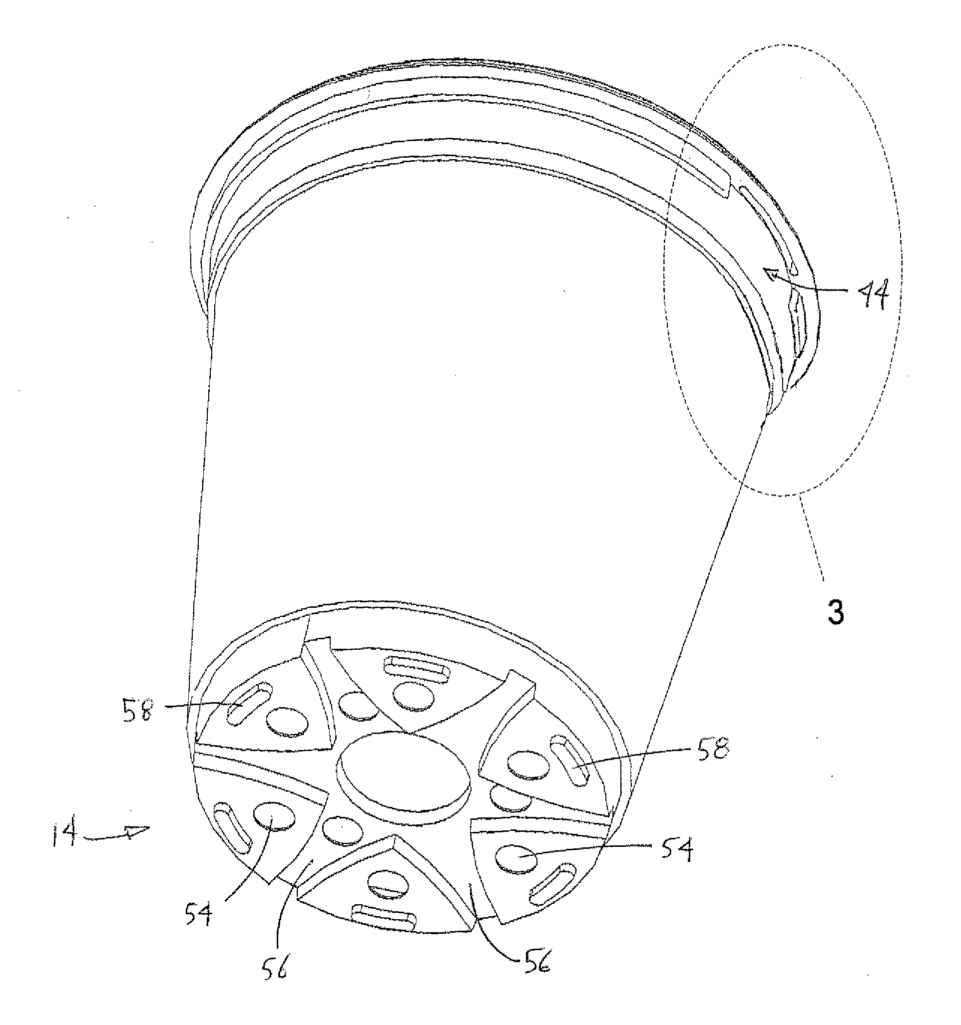
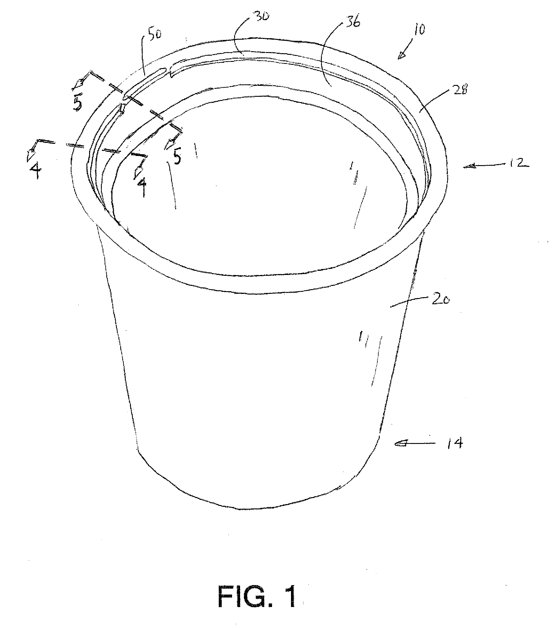
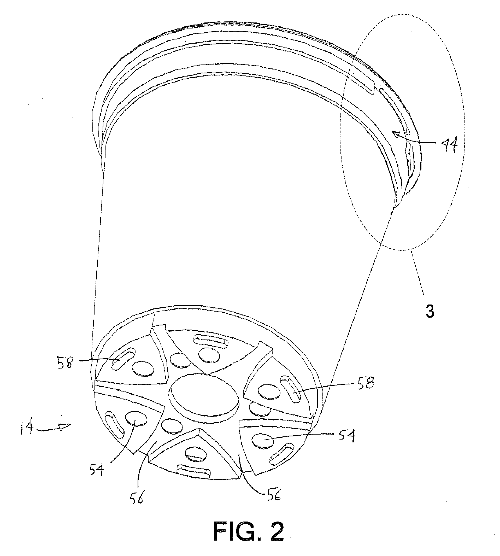
[0020] Referring now to FIGS. 1-3, one embodiment of a plant container of the present invention is shown. The plant container 10 has a substantially frustoconical shape having a top 12 and a bottom 14. The container top 12 is open, and the container bottom 14 is substantially closed, such that the container 10 is suitable for growing plants. In this description and in the appended claims, the term frustoconical describes a frustum, or the portion of a substantially conical shape between two parallel planes extending through or cutting through the shape. The frustoconical shape tapers according to a draft angle.

[0021] The container 10 comprises a sidewall 20, the bottom 14, and a lip 28. Between the sidewall 20 and the lip 28 is at least one nesting step. In the embodiment of FIGS. 1-3, two nesting steps are shown, but only one may be necessary. Adjacent to the lip 28 is a first nesting step 30 having a frustoconical first step wall 32 and a horizontally extending first step ledge 3...


PUM


Abstract

A plant container having a frustoconical sidewall extending outwardly and vertically from a bottom of the container to a top of the container, a lip positioned near the top of the container, and a tag-accepting slot formed in the lip. The container may also include a first nesting step located below the lip and extending circumferentially around the container, the nesting step extending outwardly to a maximum circumference and including a container-stacking stop surface extending between the sidewall and the maximum circumference and a extending vertically from the maximum circumference. Further, the slot may substantially be positioned above a slot area, the slot area being an area where the maximum circumference of the nesting step is reduced

Description

[0001] This application claims priority to provisional application Ser. No. 60 / 745,804, filed Apr. 27, 2006, the disclosure of which is hereby incorporated by reference.BACKGROUND [0002] Growers that raise plants for retail sale commonly use containers or pots. By growing plants in containers, growers benefit in ease of transporting and managing the plants. Further, plants grown in containers or pots are less susceptible to root damage than field grown plants that are potted for sale. [0003] One problem with plant containers is the difficulty in knowing what type of plant is in the pot. The beneficial ease of transporting the container exacerbates the identification problem when containers from one location are mixed with containers from other locations. [0004] Growers and container manufacturers have devised a variety of plant identification tags and methods for applying the tags to their respective containers. Some tags are inserted into the soil adjacent to the plant, some tags a...

Claims


Application Information

Patent Timeline
Patent Type & Authority Applications(United States)
IPC IPC(8): A01G9/02
CPCA01G9/02
Inventor SCHROMM, FRED
Owner LANDMARK PLASTIC
Why Eureka
Try Eureka