
Implant for securing neighbouring bone plates

a technology for neighbouring bone plates and implants, applied in the field of implants for securing neighbouring bone plates, can solve the problems of irritation of surrounding tissue, connection region or will be felt, etc., and achieve the effects of preventing tensioning elements, height increases, and reducing heigh

Active Publication Date: 2007-10-25
AESCULAP AG
View PDF44 Cites 139 Cited by
  • Summary
  • Abstract
  • Description
  • Claims
  • Application Information

AI Technical Summary

Benefits of technology

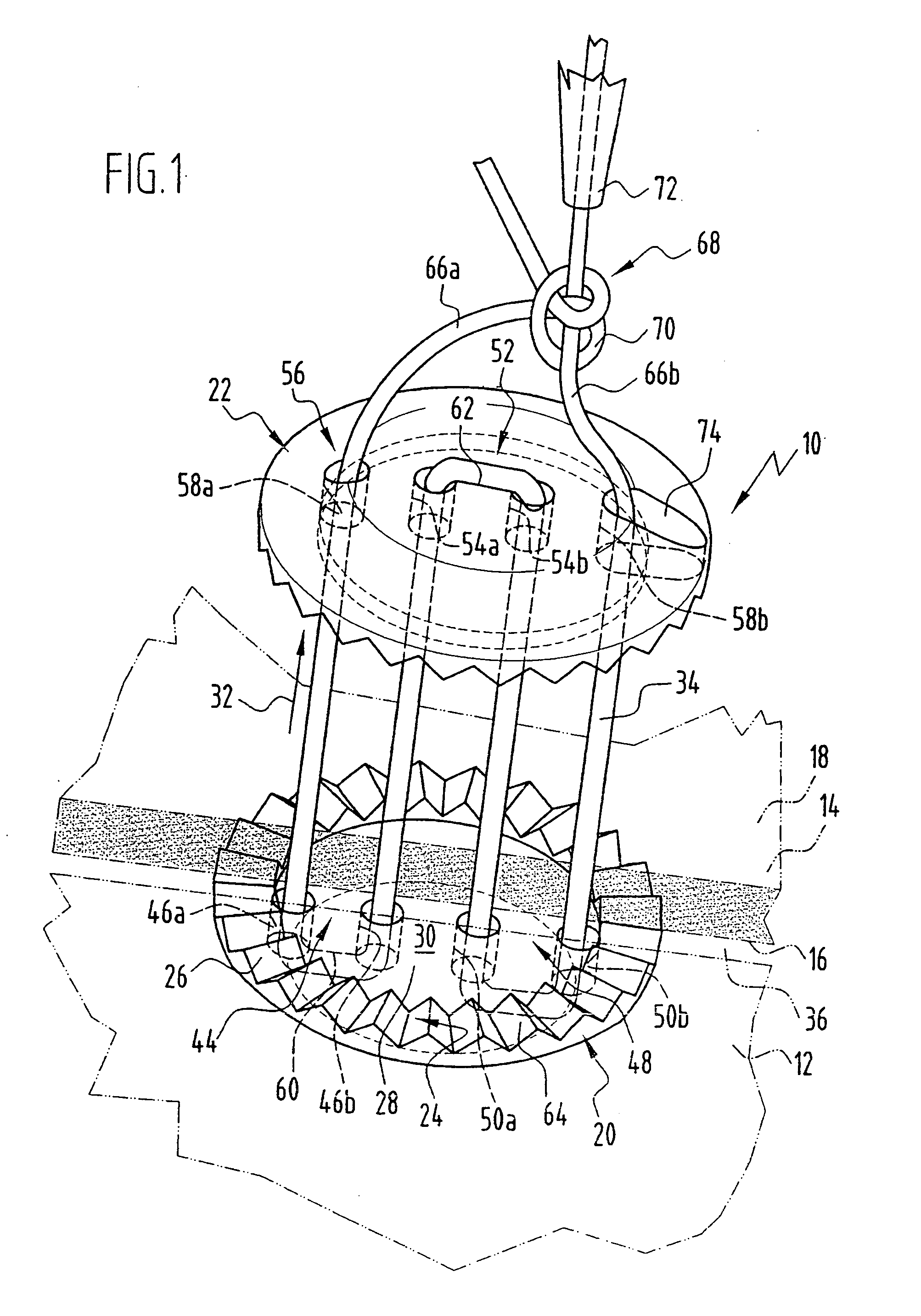
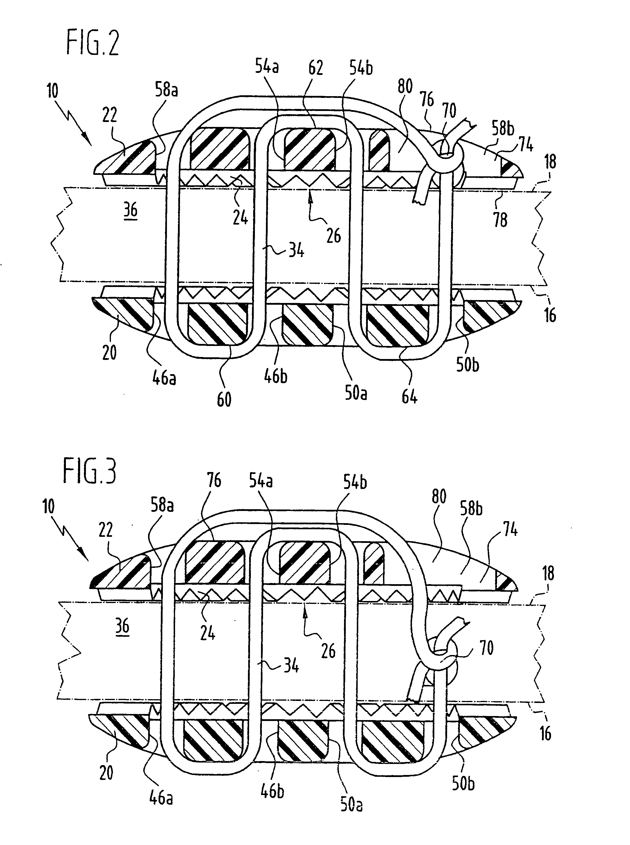
[0009] The free strands of the flexible linear tensioning element which, in particular, is a thread or a wire are linked by means of the connection region. The resultant formation such as a knot for example, can lead to irritation of the surrounding tissue or there is a danger that this connection region is or will be felt by a patient. In accordance with the invention, there is provided at least one recess with the aid of which the connection region is adapted to be at least partially countersunk relative to the outer surface of the outer contact element. As a consequence thereof, protrusion of the connection region above the outer contact element can be prevented or at least reduced, and thus in turn, tissue irritations can be prevented or at least reduced.
[0040] In particular the gripping area is arranged in peripheral manner, i.e. it is arranged around the periphery of the corresponding contact element. This thus results in a symmetrical arrangement of the contact element which simplifies its employment.

Problems solved by technology

The resultant formation such as a knot for example, can lead to irritation of the surrounding tissue or there is a danger that this connection region is or will be felt by a patient.

Method used


Image

  • Implant for securing neighbouring bone plates
  • Implant for securing neighbouring bone plates
  • Implant for securing neighbouring bone plates

Examples


Embodiment Construction

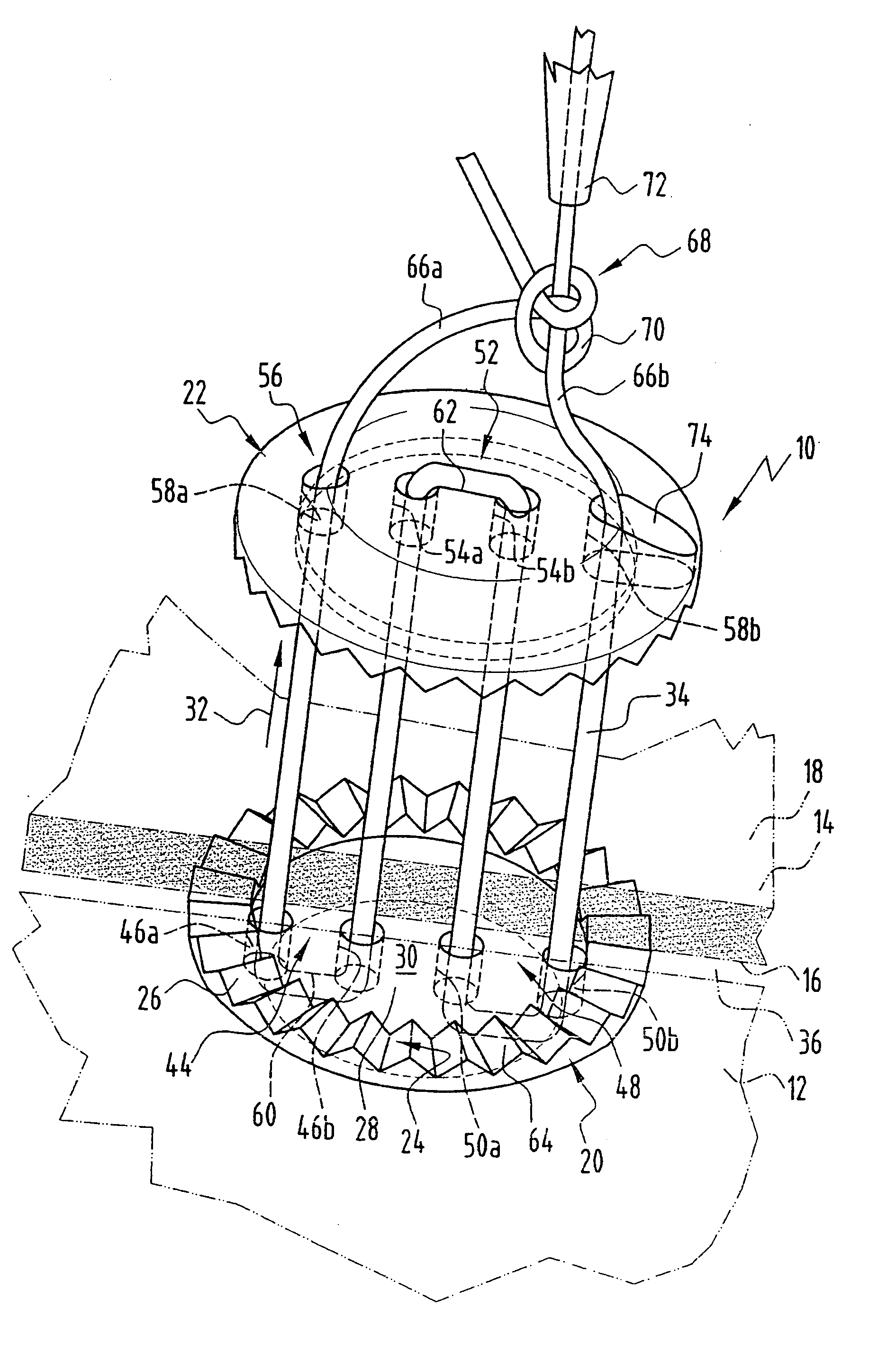
[0050] A first exemplary embodiment of an implant in accordance with the invention is shown in FIGS. 1 to 3 and bears the general reference 10 therein. The implant serves for securing neighbouring bone plates 12, 14. The bone plates 12, 14 are, in particular, cranial bone plates; for brain operations, a cranial bone plate is sawn out in order to gain access to the brain. After completion of the brain operation, the cranial bone plate that had been removed (for example the bone plate 12) must be fixed back to the bone plates surrounding it (for example the bone plate 14 and further bone plates). This is effected with the aid of a plurality of implants 10.

[0051] The bone plates 12, 14 each have an inner surface 16 and an opposite outer surface 18. The inner surface 16 faces towards the interior of the body; in the case of a cranial bone plate, the inner surface 16 faces towards the brain.

[0052] The implant 10 comprises an inner contact element 20 that is adapted to rest on the inner...


PUM


Abstract

To provide an implant for securing neighbouring bone plates, especially neighbouring cranial bone plates, wherein the bone plates each have an inner face and an outer face, comprising an inner contact element that is adapted to rest on the inner faces of the neighbouring bone plates, an outer contact element that is adapted to rest on the outer faces of the neighbouring bone plates, and an in a linear manner flexible tensioning element for connecting the inner contact element and the outer contact element in such a manner that they can no longer be separated from one another, with improved properties, it is provided that the outer contact element comprises at least one recess for at least partially accommodating a connection region between free strands of the tensioning element or for feeding the connection region through into a separation gap between the neighbouring bone plates.

Description

[0001] This application is a continuation of international application number PCT / EP2005 / 005738 filed on May 27, 2005. [0002] The present disclosure relates to the subject matter disclosed in international application number PCT / EP2005 / 005738 of May 27, 2005 and German application number 10 2004 038 823.7 of Aug. 4, 2004, which are incorporated herein by reference in their entirety and for all purposes.BACKGROUND OF THE INVENTION [0003] The invention relates to an implant for securing neighbouring bone plates, especially neighbouring cranial bone plates, wherein each of the bone plates has an inner face and an outer face, comprising an inner contact element that is adapted to rest on the inner face of the neighbouring bone plates, an outer contact element that is adapted to rest on the outer faces of the neighbouring bone plates and an in a linear manner flexible tensioning element for connecting the inner contact element and the outer contact element in such a manner that they can ...

Claims


Application Information

Patent Timeline
Patent Type & Authority Applications(United States)
IPC IPC(8): A61B17/58A61B17/00A61B17/04A61B17/68
CPCA61B17/683A61B17/688A61B17/809A61B17/808A61B2017/00004A61B2017/0474A61B17/842A61B17/04A61B17/68
Inventor WEISSHAUPT, DIETERSTEINHILPER, KLAUS-DIETERLERCH, KARL-DIETER
Owner AESCULAP AG
Learn More