
Detecting objects within a near-field of a frequency modulated continuous wave (FMCW) radar system

a radar system and frequency modulated continuous wave technology, applied in the field of radar, can solve the problems of inconvenient ranging or detecting of fmcw radars in the near-field, the inability of fmcw radar systems and the inability of fmcw radars to distinguish between objects and nois

Active Publication Date: 2007-10-25
BANNER ENG
View PDF3 Cites 28 Cited by
  • Summary
  • Abstract
  • Description
  • Claims
  • Application Information

AI Technical Summary

Benefits of technology

[0009] In general terms, the present disclosure relates to a system and method for proximity sensing, and more parti

Problems solved by technology

However, FMCW systems cannot range objects in a near-field.
When objects are in the near-field, an FMCW radar system cannot distinguish between objects and noise.
Accordingly, FMCW radars are not useful for ranging or detecting objects in the near-field.

Method used


Image

  • Detecting objects within a near-field of a frequency modulated continuous wave (FMCW) radar system
  • Detecting objects within a near-field of a frequency modulated continuous wave (FMCW) radar system
  • Detecting objects within a near-field of a frequency modulated continuous wave (FMCW) radar system

Examples


Embodiment Construction

[0022] Various embodiments of the present invention will be described in detail with reference to the drawings, wherein like reference numerals represent like parts and assemblies throughout the several views. Reference to various embodiments does not limit the scope of the invention, which is limited only by the scope of the claims attached hereto. Additionally, any examples set forth in this specification are not intended to be limiting and merely set forth some of the many possible embodiments for the claimed invention.

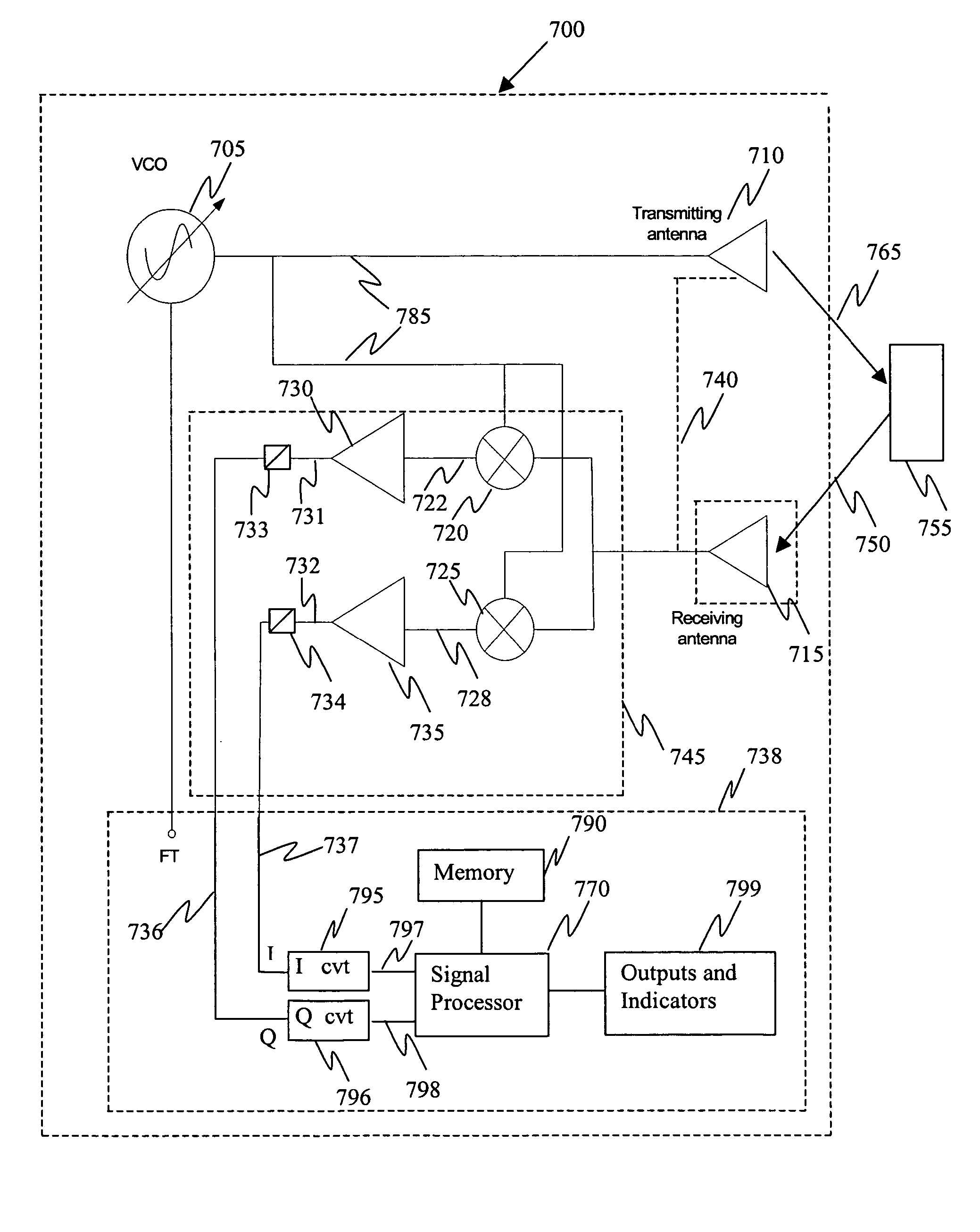
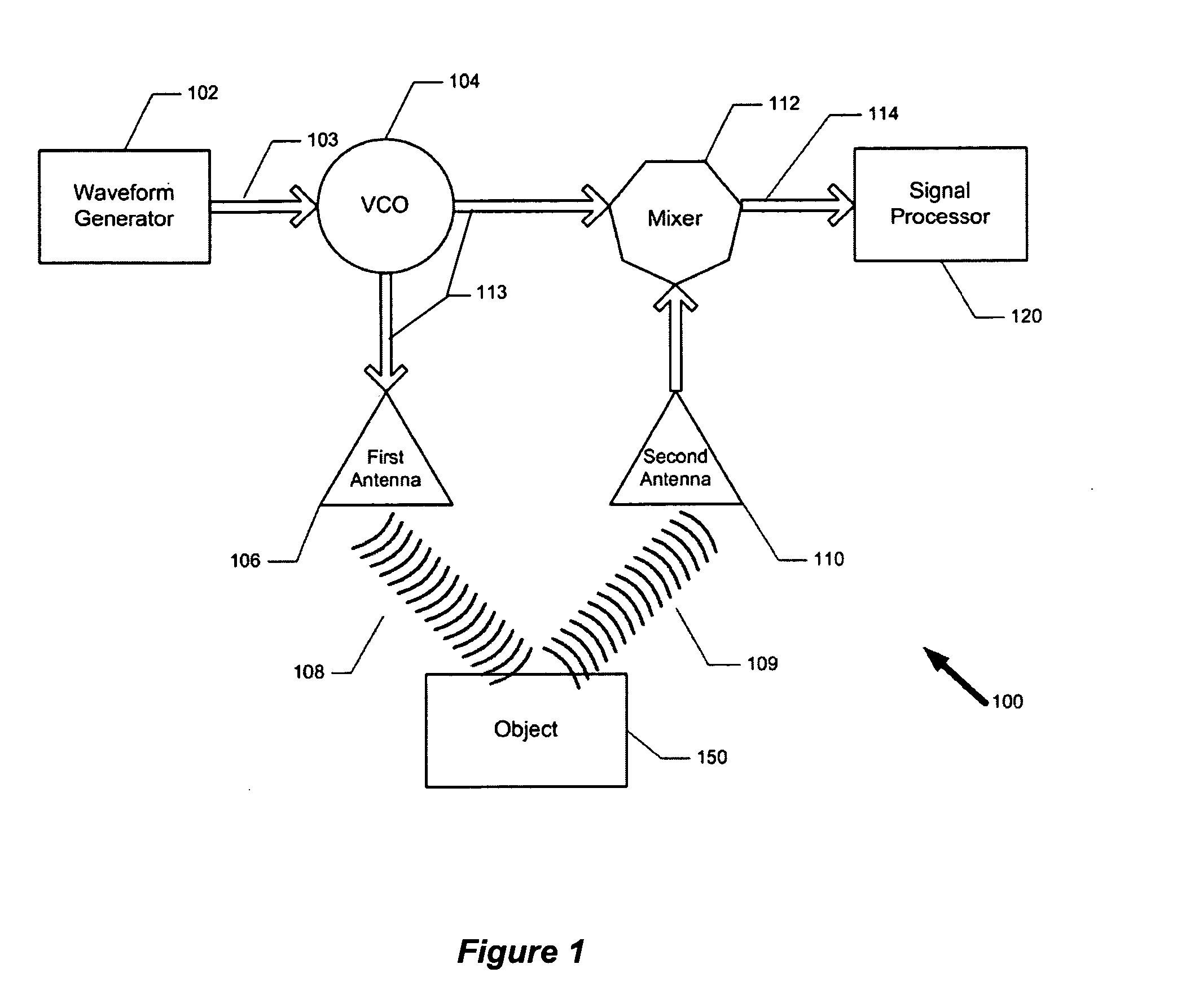
[0023]FIG. 1 is an illustration of a FMCW radar system 100 according to one possible embodiment of the present disclosure. The FMCW radar system includes a waveform generator 102 coupled to a voltage-controlled oscillator (VCO) 104. The waveform generator 102 provides a periodic input signal 103, variable with an applied voltage, to a desired repeating carrier waveform of the VCO 104. The system also includes a transmitting antenna 106, a receiving antenna 110, on...


PUM


Abstract

The present disclosure relates to a radar device and technique for detecting the presence of objects located in the near-field of a frequency modulated, continuous wave (FMCW) radar device. The technique includes transmitting and receiving a frequency modulated signal, generating an intermediate frequency signal based on the transmitted and received signals, and analyzing the frequency content of the intermediate frequency signal. The frequency content of the intermediate signal is analyzed without filtering out a carrier signal.

Description

TECHNICAL FIELD [0001] The present invention relates to radar and, more particularly to detecting objects within the near-field of a frequency modulated continuous wave (FMCW) radar system. BACKGROUND [0002] Radar is the technique of using radio waves to detect the existence of an object and then to find the object's position in relation to a known point. Air traffic control uses radar to track planes both on the ground and in the air, and also to guide planes in for smooth landings. Police use radar to detect the speed of passing motorists. The military uses it to detect an enemy and to guide weapons. NASA uses radar to map the Earth and other planets, to track satellites and space debris, and to help with docking and maneuvering of spacecrafts. [0003] Radar systems typically operate by emitting, for example, microwave energy from a transmitting antenna in the form of a focused beam with known divergence angles. Some of this emitted microwave energy is reflected off objects in the ...

Claims


Application Information

Patent Timeline
IPC IPC(8): G01S13/08
CPCG01S7/352G01S2007/358G01S2007/356G01S13/34G01S7/358G01S7/356
Inventor MICHAEL, DEANHAOZHE, DONG
Owner BANNER ENG
Learn More