
Force and Location Sensitive Display

a display and location technology, applied in the field of force and location sensitive display, can solve the problems of not being able to report a single not being able to track multiple points of contact simultaneously, and not being able to provide general pressure or force information, etc., to achieve the effect of reducing the visual aspect of the deformable member

Active Publication Date: 2007-10-11
APPLE INC
View PDF99 Cites 254 Cited by
  • Summary
  • Abstract
  • Description
  • Claims
  • Application Information

AI Technical Summary

Benefits of technology

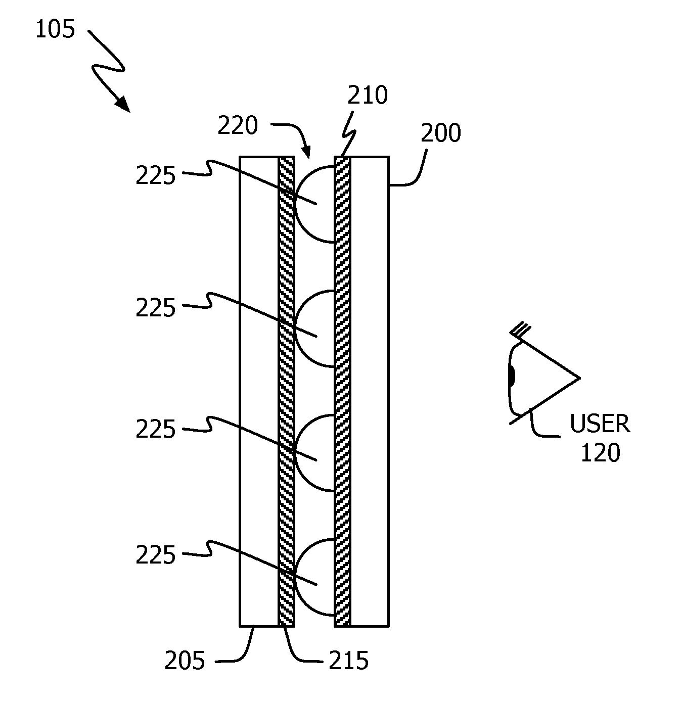
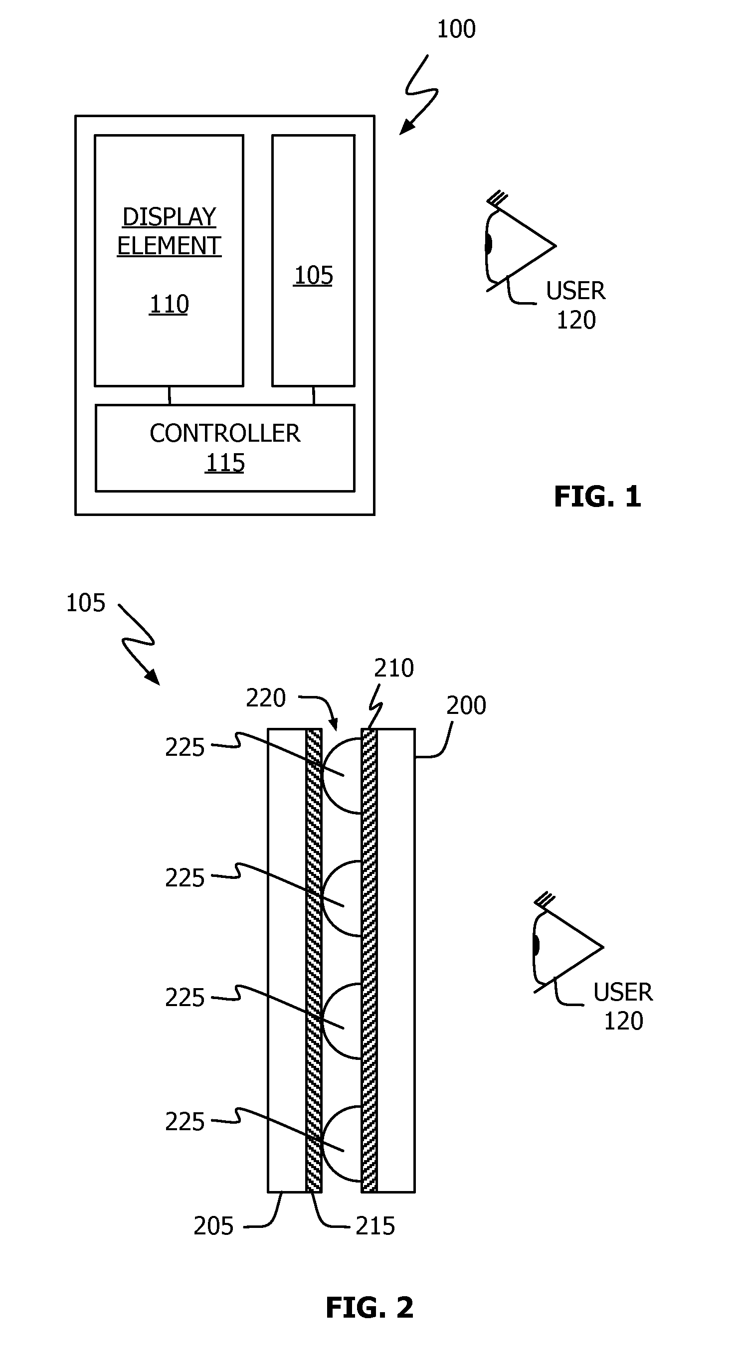
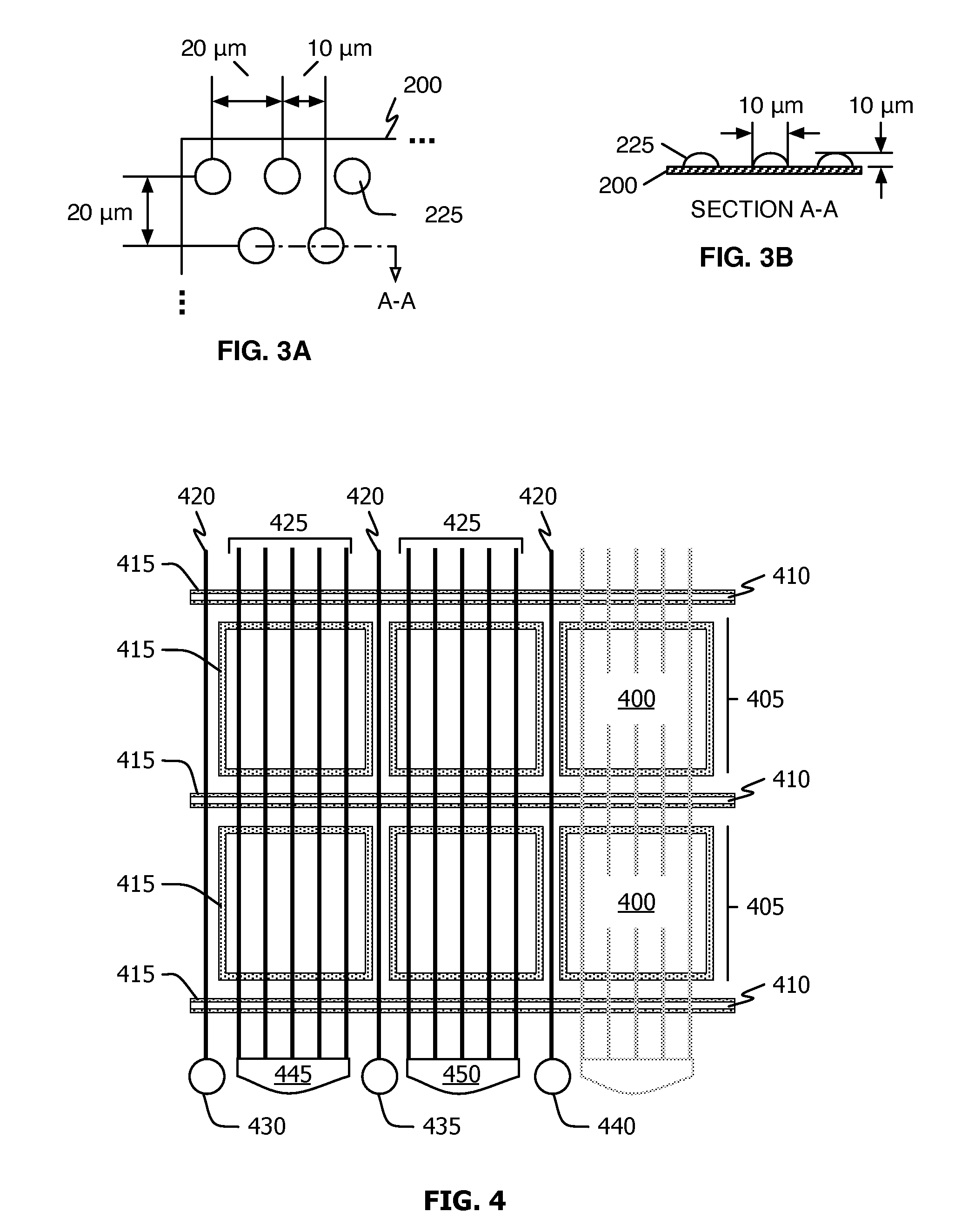
[0008] A unit to provide both force and location detection includes a first transparent substrate (having first and second sets of conductive traces oriented in a first direction), a second transparent substrate (having a third set of conductive traces oriented in a second direction) and a plurality of deformable members (e.g., rubber beads) juxtaposed between the first and second transparent substrates. The first set of conductive traces, in combination with the conductive traces of the second transparent element, are configured to provide a capacitance signal representing where a user touches the display element. The second set of conductive traces, in combination with the conductive traces of the second transparent element, are configured to provide a capacitance signal representing the amount of force applied to the display element. In one embodiment, the second transparent substrate includes a fourth plurality of conductive traces (oriented in the second direction), each pair of which separates sets of the third plurality of conductive traces. In another embodiment, the two transparent substrates form a closed volume that may be filled with a liquid to mitigate visual aspects of the deformable members. The described force and location sensitive unit may be abutted to a display element (e.g., a LCD or CRT) so that a display unit providing both location sensing and force sensing is possible.

Problems solved by technology

One drawback to these technologies is that they do not generally provide pressure or force information.
Another problem with these technologies is that they are only capable of reporting a single point even when multiple objects are placed on the sensing surface.
That is, they lack the ability to track multiple points of contact simultaneously.

Method used


Image

  • Force and Location Sensitive Display
  • Force and Location Sensitive Display
  • Force and Location Sensitive Display

Examples


Embodiment Construction

[0015] The following description is presented to enable any person skilled in the art to make and use the invention as claimed and is provided in the context of the particular examples discussed below, variations of which will be readily apparent to those skilled in the art. Accordingly, the claims appended hereto are not intended to be limited by the disclosed embodiments, but are to be accorded their widest scope consistent with the principles and features disclosed herein.

[0016] Referring to FIG. 1, force and location display unit 100 in accordance with one embodiment of the invention comprises novel force and touch cell 105, display element 110 and controller 115. As shown, cell 105 is juxtaposed in front of display element 110 (from the perspective of user 120). For example, cell 105 may be laminated to the front of display element 110. Illustrative display element 110 includes, but is not limited to, various types of liquid crystal displays (“LCD”, plasma displays and cathode...


PUM


Abstract

A unit to provide both force and location detection includes a first transparent substrate (having first and second sets of conductive traces oriented in a first direction), a second transparent substrate (having a third set of conductive traces oriented in a second direction) and a plurality of deformable members (e.g., rubber beads) arranged between the first and second transparent substrates. The first set of conductive traces, in combination with the conductive traces of the second transparent element, provide a capacitance signal representing where a user touches the display element. The second set of conductive traces, in combination with the conductive traces of the second transparent element, provide a capacitance signal representing the amount of force applied to the display element. When used with a display element (e.g., a LCD or CRT), an input-output unit capable of both location sensing and force sensing operations is provided.

Description

CROSS-REFERENCE TO RELATED [0001] This application claims priority to U.S. patent applications entitled “Force imaging Input Device and System,” filed 30 Mar. 2006 (Ser. No. 11 / 278,080) and “Multipoint Touchscreen,” filed 6 May 2004 (Ser. No. 10 / 840,862) and which are hereby incorporated by reference.BACKGROUND [0002] This invention relates generally to electronic system input and output devices and, more particularly, to a display unit (output) that detects a user's touch and the force of the touch (input). [0003] There exist today many styles of input devices for performing operations in a computer system. The operations generally include moving a cursor and / or making selections on a display screen. By way of example, input devices may include buttons or keys, mice, trackballs, touch pads, joy sticks and touch screens. Touch screens, in particular, are becoming increasingly popular because of their ease and versatility of operation as well as to their declining price. Touch screen...

Claims


Application Information

Patent Timeline
IPC IPC(8): G06F3/041
CPCG06F3/044G06F3/0414G06F3/0447G06F3/0445
Inventor HOTELLING, STEVE P.
Owner APPLE INC
Learn More