
Station-side apparatus of wavelength multiplexing PON system, wavelength and network address allotting method and program thereof

a wavelength and network address technology, applied in the field of station-side apparatus of wavelength multiplexing optical access network, can solve the problems of increasing the setting time, wasting wavelength resources, and setting errors, and achieve the effect of saving the resources of wavelength and network address, efficient network control, and excellent

Inactive Publication Date: 2007-10-04
NEC CORP
View PDF11 Cites 31 Cited by
  • Summary
  • Abstract
  • Description
  • Claims
  • Application Information

AI Technical Summary

Benefits of technology

[0009]The object of the present invention is to improve the shortcomings of the above-described conventional case. Specifically, it is to provide a station-side apparatus of a wavelength multiplexing PON system, a wavelength and network allotting method, and a program thereof, which are capable of allotting the wavelength and the network address simultaneously, reducing the work for the allotment (setting for allotting those dynamically), and saving the wavelength resources.

Problems solved by technology

It has been a big issue to achieve broadband of the access circuits due to a rapid spread of the Internet.
Thus, there requires a lot of work, so that there may generate a setting error.
This leads to a complication and an increase in the setting time.
In addition, it leads to wasting the wavelength resources, since the wavelength is also allotted to the ONUs that are not being used.

Method used


Image

  • Station-side apparatus of wavelength multiplexing PON system, wavelength and network address allotting method and program thereof
  • Station-side apparatus of wavelength multiplexing PON system, wavelength and network address allotting method and program thereof
  • Station-side apparatus of wavelength multiplexing PON system, wavelength and network address allotting method and program thereof

Examples


Embodiment Construction

[0053]An embodiment of the present invention will be described hereinafter by referring to the accompanying drawings.

[0054]The outline of the PON system that is the technical basis of this embodiment will be described first, and the contents of the embodiment will be described in detail thereafter.

(Basic Structure of PON system)

[0055]FIG. 19 and FIG. 20 illustrate the basic structure of the PON system and the flow of the signals transmitted therein.

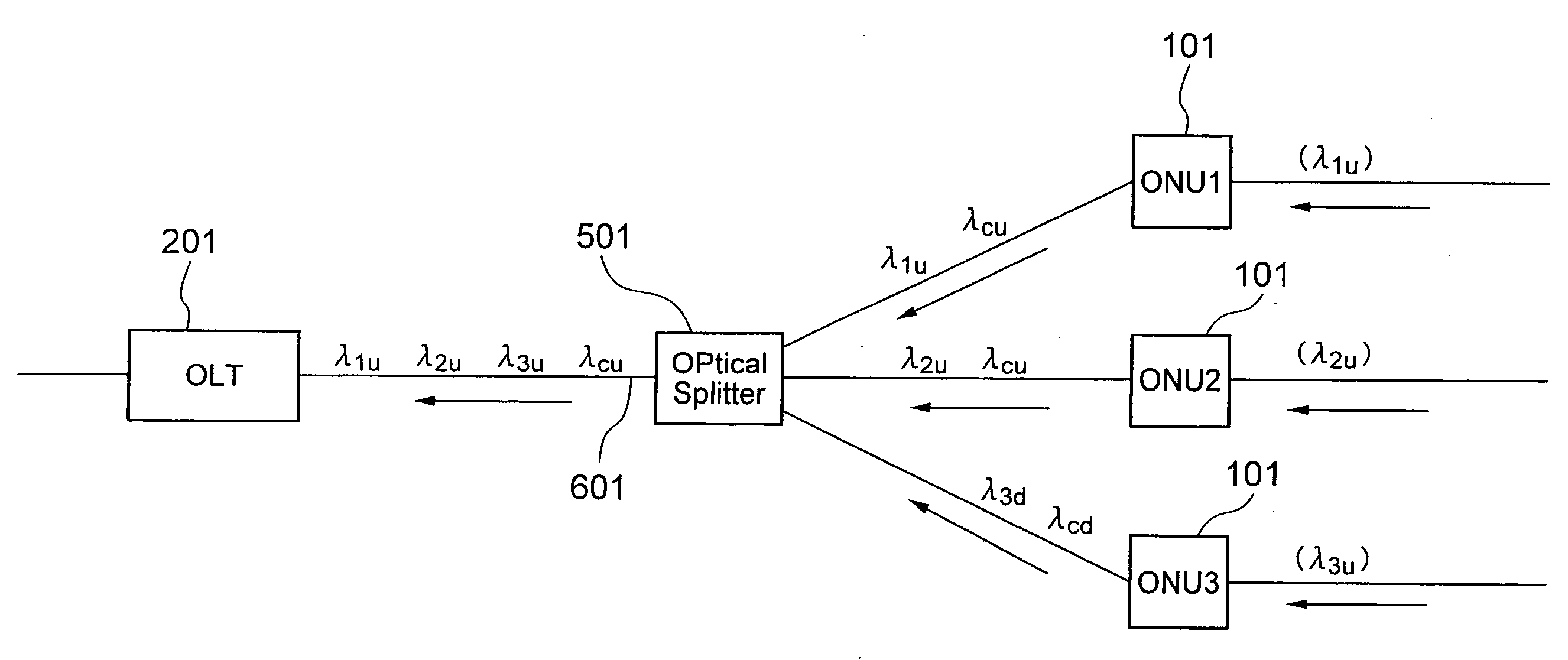
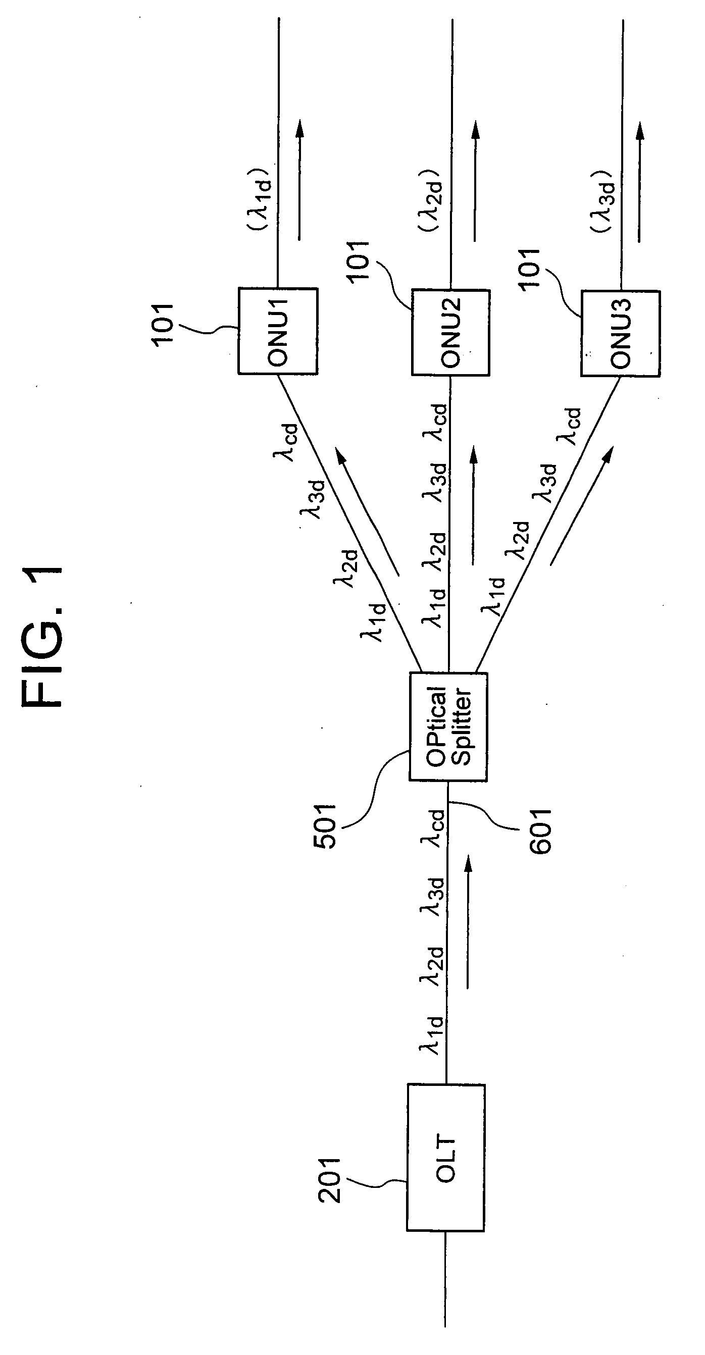
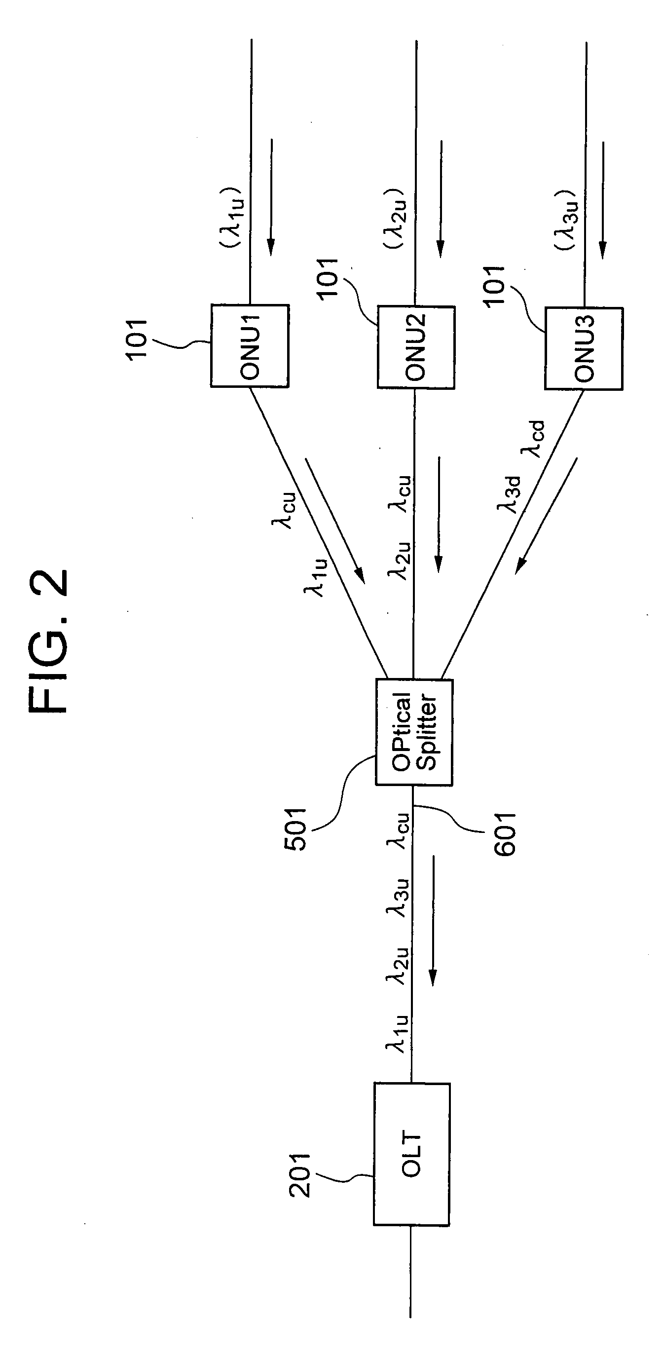
[0056]In FIG. 19 and FIG. 20, reference numeral 401 is a station-side apparatus (OLT), 301 is an in-home apparatus (ONU), 501 is an optical splitter, and 601 is an optical fiber.

[0057]As shown in FIG. 19 and FIG. 20, the ONU 301 is placed at each end-user's home, and the OLT 401 is placed at the station. The ONUs 301 and the OLT 401 are connected via the optical fiber 601 and the optical splitter 501. Personal computers of each user are connected to the network via the ONU 301, which are connected further to the higher network and the Int...


PUM


Abstract

To achieve a station-side apparatus of a wavelength multiplexing PON system, which is capable of saving the wavelength resource through automatically carrying out allotment of the wavelength and the network address to reduce the complicated work for the setting, and through dynamically allotting the wavelength without fixing it in advance. It is a station-side apparatus (OLT) of a wavelength multiplexing PON system that comprises a plurality of in-home apparatuses (ONUs). The station-side apparatus is connected to the in-home apparatuses via transmission paths including an optical multiplexing distributor, and executes allotment of the wavelength in response to wavelength allotment requests from the in-home apparatuses. The station-side apparatus comprises a wavelength / network address allotting device that is provided with a DHCP server in advance, which dynamically allots wavelength and network address to the in-home apparatus in response to the wavelength allotment request from the in-home apparatus.

Description

BACKGROUND OF THE INVENTION[0001]1. Field of the Invention[0002]The present invention relates to a station-side apparatus of a wavelength multiplexing optical access network, a wavelength and network address allotting method executed by the station-side apparatus, and a program thereof. More specifically, the present invention relates to a station-side apparatus of a wavelength division multiplexing PON (Passive Optical Network) system, a wavelength and network address allotting method in the system, and a program thereof.[0003]2. Description of the Related Art[0004]It has been a big issue to achieve broadband of the access circuits due to a rapid spread of the Internet. Various systems such as ADSL, cable modems, and the like have already been put into practical use as the broadband access circuits. However, the passive optical network (PON) has drawn an attention for achieving a still broader band.[0005]The PON is a network where a plurality of users share a single optical fiber b...

Claims


Application Information

Patent Timeline
IPC IPC(8): H04J14/00H04B10/27H04B10/272H04J14/02H04L12/44
CPCH04J14/0226H04J14/0227H04J14/0282H04L61/2015H04J14/0246H04Q2011/0064H04J14/025H04J14/0252H04J14/0232H04Q11/0067H04L61/5014
Inventor OZAKI, HIROKAZU
Owner NEC CORP
Learn More