
Integrated, self-contained power distribution system

a power distribution system and self-contained technology, applied in the direction of substation/switching arrangement details, electrical equipment, substation/switching arrangement casings, etc., can solve the problems of large-scale construction, large-scale construction, and inability to meet the needs of emergency power sources, so as to facilitate repeatable, reusable wiring of power distribution circuits, and facilitate quick installation and removal.

Inactive Publication Date: 2007-10-04
CARLSON CURT S
View PDF7 Cites 57 Cited by
  • Summary
  • Abstract
  • Description
  • Claims
  • Application Information

AI Technical Summary

Benefits of technology

[0018]A further object of the present invention is to provide an affordable, temporary power service and distribution system that is fully protected for a wide variety of different voltage levels.
[0021]It is yet a further object of the present invention to provide a temporary, portable, power service and distribution system in which individual circuits can be monitored and controlled.
[0024]It is again a further object of the present invention to provide a temporary, portable power service and distribution system that is easily sectionalized into subcircuits or subunits.
[0025]It is yet an additional object of the present invention to provide a temporary, portable power service and distribution system that facilitates a repeatable, reusable method of wiring power distribution circuits at different locations.
[0026]It is again another object of the present invention to provide a temporary, portable power service and distribution system that facilitates quick installation and removal for reuse.

Problems solved by technology

Emergency power sources are generally not designed to handle the entire load of the regular power source.
Further, such devices are not present in temporary or emergency arrangements that are normally cobbled together with any components that are readily available.
The lack of power allocation equipment is particularly problematical since most emergency situations require careful power allocation.
Because extensive construction is time-consuming, long-term arrangements are often necessary, even with a temporary power service arrangement.
Very often such arrangements are inappropriate for reuse (not repeatable), since they are installed very informally, often with random components, and with virtually no safeguards against weather or other hazards.
Unfortunately a tradition has evolved in the building industry whereby a minimum amount of effort in effecting temporary power service and distribution connection arrangements has become accepted practice.
In many cases temporary electrical power service and down stream distribution connections are made using old, often questionable circuit breaker boxes mounted on temporary plywood supports that have been erected in close proximity to the regular connections from the local electrical power system.
Very often they are made without adequate protection from the weather or other hazards.
However, one cannot always count on optimum conditions to avoid the results of questionable temporary power connections, especially in extreme environmental conditions.
For example, in bad weather, a temporary circuit breaker box or similar arrangement may leak, causing a massive short at the main input point.
Wet conditions can also lead to multiple fault conditions down line from the circuit breaker box.
Any of this can lead to overloaded circuits, and even to fires.
Further, most temporary power distribution arrangements provide only standard house voltage on a few circuits with limited load capacity.
Very often, power use on temporary connections will far exceed that originally planned upon.
Conventionally, there is very little that can be done to increase capacity once the temporary power service has been energized.
Conventional temporary power service arrangements also do not address situations involving, line monitoring, or programmed power use.
Further, there is no provision for alarm systems or any kind of telephone connection related to the control and monitoring of the power system.
Also, conventional temporary power service and distribution arrangements do not provide for low voltage applications, such as emergency lighting, or control systems, generator backup sets, closed circuit TV, security circuits for alarms, and rectified 12 volt DC for hazardous duty.
In conventional temporary power distribution arrangements, there is no way to monitor power usage on any more than the main circuit (with a power company meter), so that sources of excessive usage cannot be easily isolated in an extended service area.
Conventional temporary arrangements also do not accommodate battery packages necessary for low voltage applications or necessary for uninterruptible power supplies.
Nor is there any accommodation for the types of controls such a system would require.
Most temporary power connections are not portable.
If that location is suddenly found to be inconvenient due to unforeseen conditions, movement of the temporary distribution system could become problematical after activation of the temporary connections.
Following standard practice, attempted movement would be either very time-consuming, or very unsafe.
As a result, many temporary power service connections are questionable at best and disastrous at worst.
Once problems do occur, it is usually impossible to separate sections of the system from each other with conventional temporary power service and distribution arrangements.
Consequently, the entire temporary power grid (including both permanent and temporary elements) must be deactivated, rather than just those sections that might be problematical.
Even if a building under construction has a fully completed control, alarm, or power conservation system, these cannot be activated using conventional, temporary power service arrangements.
Likewise, there are no provisions with conventional power service arrangements for low voltage emergency lighting, telephone connections, or computer control of any aspect of the system.

Method used


Image

  • Integrated, self-contained power distribution system
  • Integrated, self-contained power distribution system
  • Integrated, self-contained power distribution system

Examples


Embodiment Construction

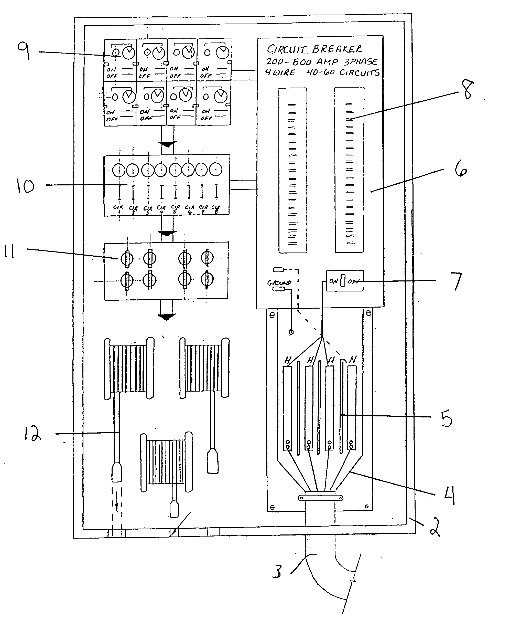
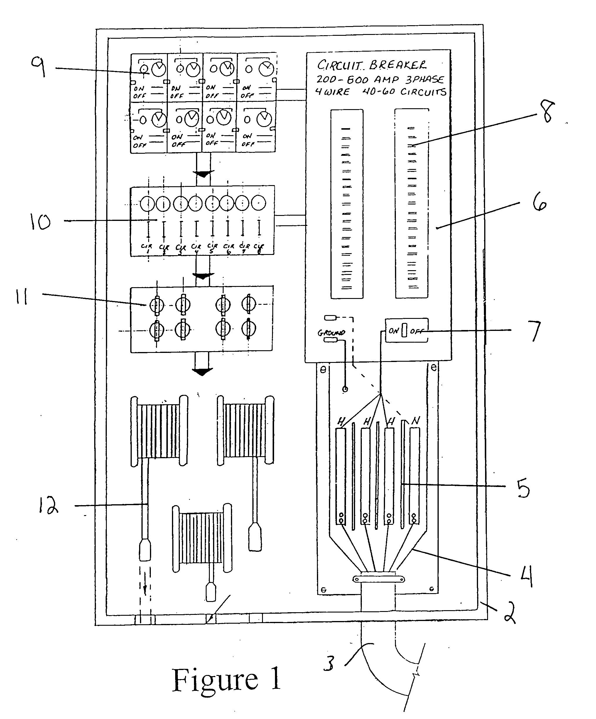
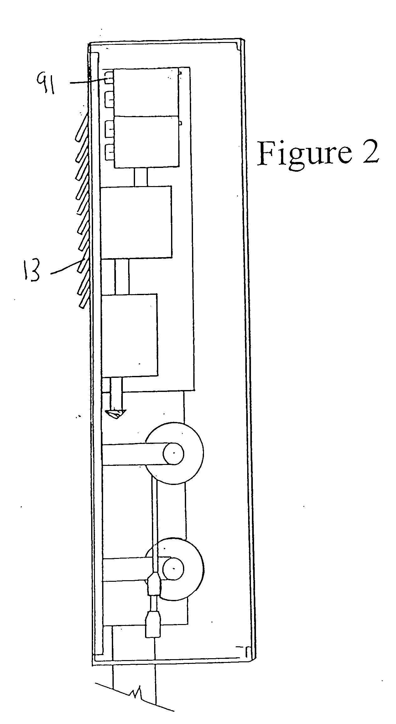
[0039]The concept of the present invention is the provision of a substitute, temporary, power service and distribution system for the regular or permanent power distribution system. The temporary or alternate power service and distribution system is connected in parallel to the regular or permanent power distribution system, between the power company source and the actual distributed load being serviced.

[0040]The entire substitute or alternative system is contained in an integrated package, providing all of the necessary functions to be found in the permanent power distribution system. The definition of “integrated” as used in this application is a package that contains all the necessary functionality found with a particular permanent power distribution system for which the present invention is substituted.

[0041]The container, enclosure or overall package contains everything necessary for a connection to an electrical power source (such as the power company). The integrated package ...


PUM


Abstract

A portable, temporary power distribution system is contained in a fully integrated, reusable container, and is particularly useful in temporary applications, especially as an alternative power distribution system. The portable system provides comprehensive functionality for all aspects of a power system, and any adjuncts thereto. The portable power distribution system is fully integrated, and can include, for example, low voltage capability, emergency lighting control, communication, power allocation control and circuit protection, as well as any other protective or control feature that is used in a permanent power distribution system for virtually any installation.

Description

FIELD OF INVENTION [0001]The present invention relates generally to arrangements for service entrance units for temporary power connections. More specifically, the present invention is directed to a safe, repeatable, comprehensive, self-contained, portable / temporary power distribution system.BACKGROUND [0002]There are many situations in which temporary or portable power arrangements are essential. The two most prevalent examples of such situations are severe environmental disruptions (such as hurricanes, tornados & fires), and construction or refurbishing projects for existing structures or installations, which have their own power distribution systems (but need temporary power distribution for construction). Other examples include military installations, field hospitals and service & repair facilities for planes & helicopters.[0003]In the first situation a temporary electric power service connection to an auxiliary power source (such as a portable generator) may be necessary to pro...

Claims


Application Information

Patent Timeline
IPC IPC(8): H02B1/26
CPCH02B1/52
Inventor CARLSON, CURT S.
Owner CARLSON CURT S
Learn More