
Gymnastic machine

a gymnastic machine and body technology, applied in the field of gymnastic machines, can solve the problems of high cost, negative impact on production costs, and complex bill of materials of gymnastic machines,

Inactive Publication Date: 2007-09-27
TECHNOGYM SPA
View PDF19 Cites 16 Cited by
  • Summary
  • Abstract
  • Description
  • Claims
  • Application Information

AI Technical Summary

Benefits of technology

[0009] The object of the present invention is to construct a gymnastic machine that allows the disadvantages described above to be solved, and which is suitable to satisfy a plurality of requirements that to date have still not been addressed, and therefore, suitable to represent a new and original source of economic interest, capable of modifying the current market of skating simulators.
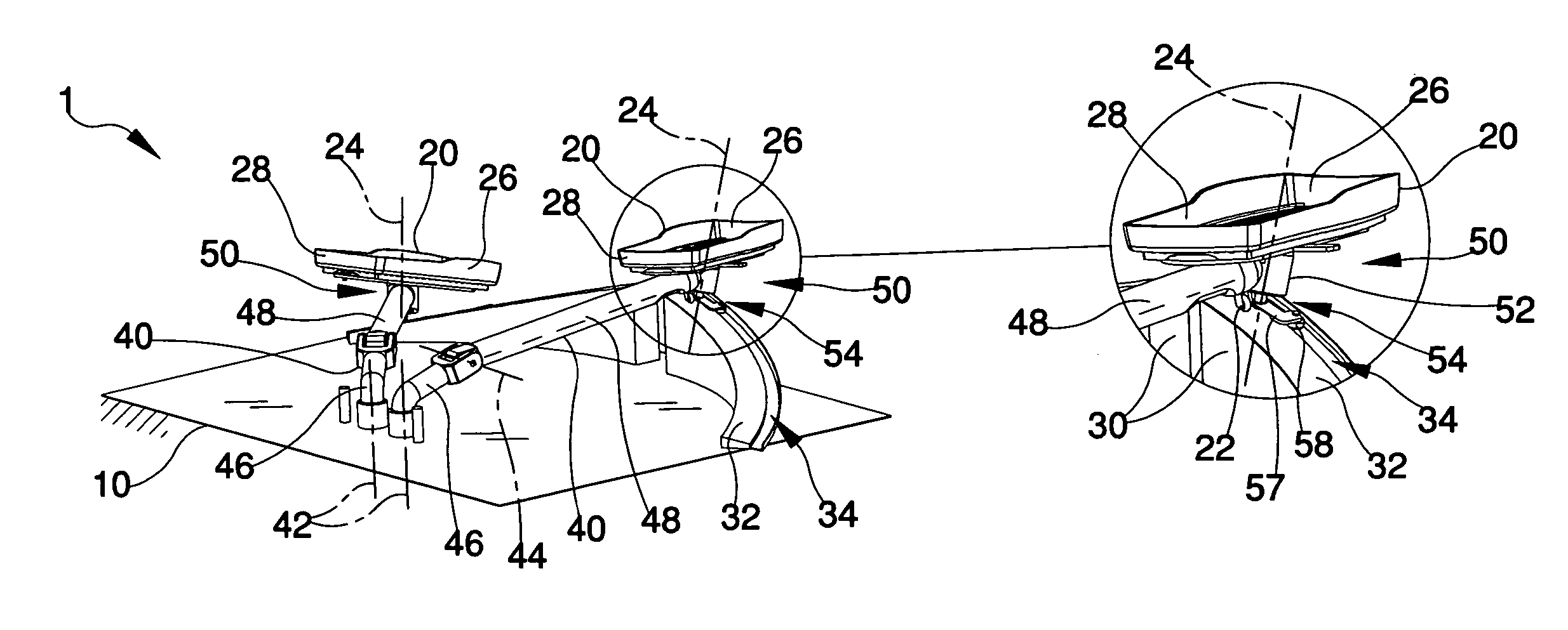
[0010] According to the present invention, there is provided a gymnastic machine a frame and a pair of footrests, each of which is movable on a shaped element designed in a given fashion along an arched trajectory (P). Each footrest is connected to the frame in open chain by means of at least an arm rotating with respect to a first axis. Each arm is provided, at a respective footrest, with a rotatable member suitable to roll on the shaped element. The gymnastic machine includes controlling means associated with each footrest for varying, in use, the orientation of the footrest so as to make the footrest capable to rotate with respect to a respective arm in the opposite direction to a rotation imposed on the arm.

Problems solved by technology

Therefore, both the arms and the relative articulated mechanisms are constructed in a different manner, making the bill of materials of the gymnastic machine particularly intricate and complex.
This peculiarity greatly increases the number of pieces of different shapes and dimensions, even if for identical functions, and thus also the amount of equipment required to produce the machine, with a negative impact on production costs.
Therefore, each footrest must have a corresponding support with a considerable cost in order to have a particularly compact mechanism in which the respective components frequently overlap one another.
In view of the above description, both in the case of the application RA2004A000044 and in the case of the application RA2004A000029, the complexity of the mechanisms corresponding to the footrests makes the corresponding machines intrinsically rather unsafe due to the overlaps that occur in the plane between the levers supporting the footrests.
The intrinsic lack of safety could cause serious injuries in the event of the user losing his / her balance and placing a foot or limb in general in the space swept by the footrests and / or by the quadrilateral components.
Furthermore, simplification of the mechanism that constrains each footrest does not allow the footrests to be moved so that they follow a correct movement of the articulation of each foot.

Method used


Image

  • Gymnastic machine
  • Gymnastic machine
  • Gymnastic machine

Examples


Embodiment Construction

[0016] In FIG. 1, number 1 indicates, in its entirety, a gymnastic machine for performing skating training exercises. The machine 1 comprises a frame 10 and a pair of footrests 20, each of which is connected to the frame 10 according to an open chain kinematic model by means of at least an arm 40, to which it is connected in an end position. Each arm 40 is carried by the frame 10 in a rotatable manner with respect to a first substantially vertical pivot axis 42 and is articulated on the side of the first axis 42 about a second pivot axis 44 substantially transverse to the first axis 42, and thus horizontal. In particular, each arm 40 comprises a first lever 46 hinged to the frame 10 at the first axis 42 and a second lever 48 hinged to the first lever 46 at the second axis 44, which carries a respective footrest 20 in an end position. The open kinematic chain corresponding to each footrest 20 and comprising the respective articulated arm 40 is closed by a shaped element 30 to give st...


PUM


Abstract

Gymnastic machine (1) is provided with a frame (10) and a pair of footrests (20), each of which is movable on a shaped element (30) designed in a given fashion along an arched trajectory (P), with each footrest (20) being connected to the frame (10) in open chain by means of at least one arm (40) rotating about a first substantially vertical axis (42), with each arm (40) being provided, at the respective footrest (20), with a rotatable member (22) suitable to roll on the shaped element (30), and a controlling device (50) is associated with each footrest (20) for varying, in use, the orientation of the footrest (20) so as to make this footrest (20) able to rotate in the opposite direction to a rotation imposed on the corresponding arm (40).

Description

BACKGROUND OF THE INVENTION [0001] 1. Field of the Invention [0002] The present invention relates to a gymnastic machine. In particular, the present invention relates to a gymnastic machine for performing skating training exercises. In more detail, the present invention relates to a gymnastic machine comprising a pair of footrests for simulating the skating movement wherein each footrest is constrained to an arm rotatably supported by a frame with respect to two axes substantially orthogonal to each other. [0003] 2. Description of the Prior Art [0004] In the field of gymnastic machines there are well-known skating simulators for training of the lower limbs particularly suitable for cardiovascular training sessions. Some machines of this type are produced in implementation of patents whose teachings have already been described and discussed in the text attached to the Italian invention patent application no. RA2004A000044 filed on 16 Sep. 2004, which corresponds to U.S. application S...

Claims


Application Information

Patent Timeline
Patent Type & Authority Applications(United States)
IPC IPC(8): A63B22/00A63B69/18
CPCA63B21/154A63B22/0064A63B23/0482A63B2022/206A63B2022/0071A63B2208/0204A63B22/203A63B69/0022
Inventor MAFFEI, ROBERTODELLA VITTORIA, FRANCESCOGORZA, ROBERTO
Owner TECHNOGYM SPA
Learn More