
Reclining chair with enhanced adjustability

a reclining chair and enhanced technology, applied in the field of ergonomic seating, can solve the problems of difficult adjustment, difficult adjustment, and inability to provide visual or tactile feedback to users, and achieve the effect of facilitating the adjustment of resistan

Active Publication Date: 2007-09-27
HNI TECH INC
View PDF36 Cites 53 Cited by
  • Summary
  • Abstract
  • Description
  • Claims
  • Application Information

AI Technical Summary

Benefits of technology

The present invention provides an adjustable reclining chair with a seat, back, and control mechanism. The control mechanism allows the user to adjust the resistance to recline the back of the chair. The chair back is connected to the seat with a pivot mechanism that allows the back to move rearward when the user applies force to it. The chair back remains in contact with the user's back to reduce shear and pull-away forces. Additionally, the invention provides an adjustable chair back with a resilient material that can be adjusted for stiffness. This allows for more comfortable and customizable reclining experience.

Problems solved by technology

These adjustments often are difficult, awkward or require an extensive amount of user work to generate perceptible changes in the tension.
In addition, most of these chairs provide no visual or tactile feedback to the user about the range of tension adjustment available and where, within this range, the chair is currently.
As a result, many users don't take full advantage of the versatility of the chair in accommodating their comfort.
The force applied to the chair back during reclining, as mentioned above, also may result in a shearing force between the user's back and the chair back.
In addition, reclining in these types of chairs may also cause a “pull-away” between the chair back and the user's back, such that the chair back does not remain in contact with the user's back as the chair reclines.
As a result, the chair fails to provide proper support causing discomfort and dissatisfaction.

Method used


Image

  • Reclining chair with enhanced adjustability
  • Reclining chair with enhanced adjustability
  • Reclining chair with enhanced adjustability

Examples


Embodiment Construction

[0044]With reference to the attached Figures, it is to be understood that like components are labeled with like numerals throughout the several Figures. Unless otherwise specified, the components described herein with respect to the present invention may be formed from any suitable material and by any suitable manufacturing method. For example, parts may be formed from plastic, such as glass-filled nylon or other moldable materials, or from die-cast aluminum.

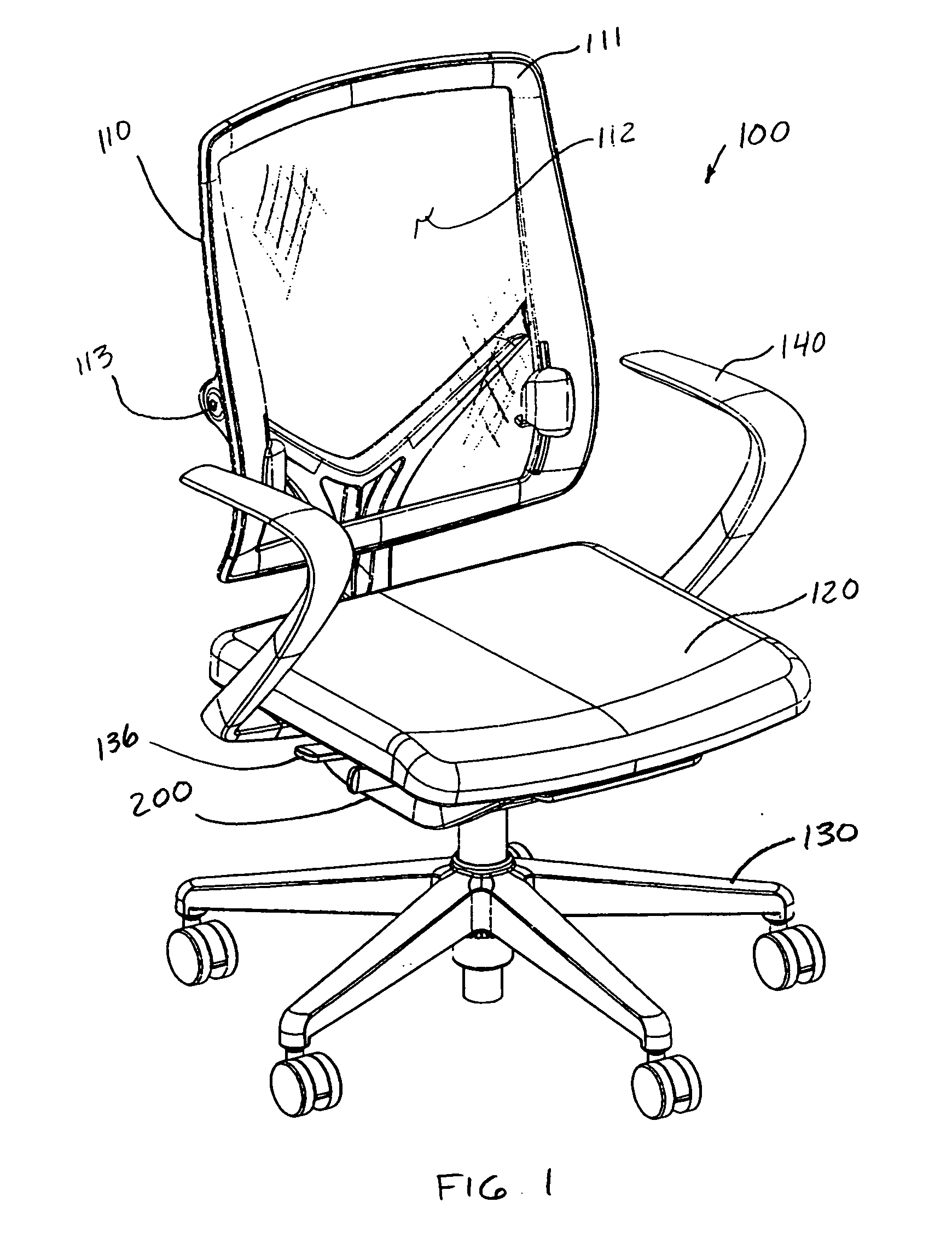
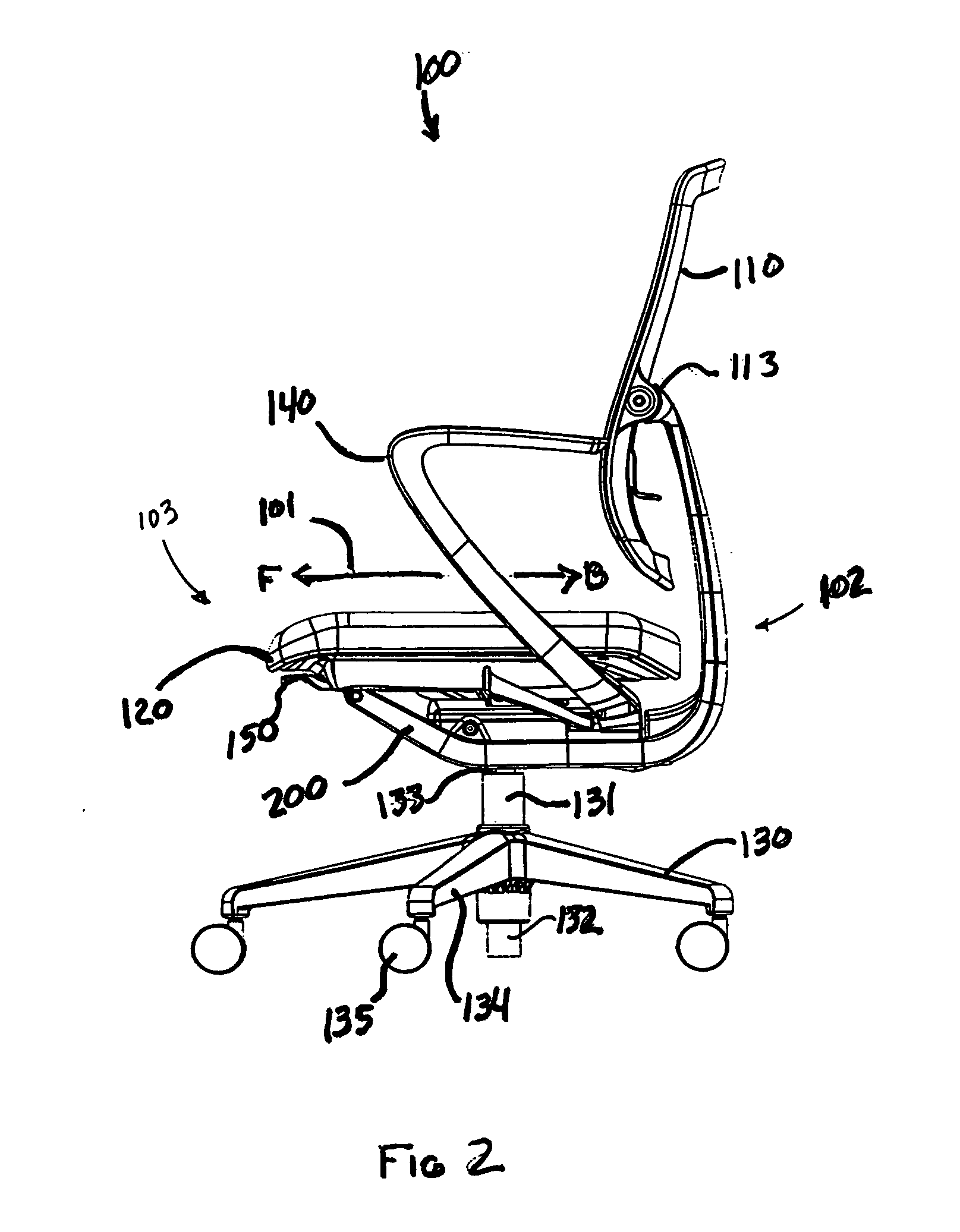
[0045]FIGS. 1-3 show a first embodiment of a reclining chair 100, and FIGS. 4-6 show a second embodiment of a reclining chair 105, in accordance with the present invention. The first chair 100 includes a back 110, a seat 120, a base 130, arms 140 and a control mechanism 200. The second chair 105 includes a back 115, a seat 120, a base 130, arms 145 and a control mechanism 200. The backs 110, 115, the seats 120 and the arms 140, 145 all attach to the control mechanisms 200, which are mounted on the bases 130. In FIGS. 1, 2, 4 and...


PUM


Abstract

An adjustable reclining chair including a seat configured to support a user, a chair back, a base and a control mechanism mounted on the base. The control mechanism coupling the chair back to the seat with the chair back located generally adjacent to the user's back when the user is seated upon the seat. The control mechanism including a resistance adjustment mechanism for varying the control mechanism's resistance to a reclining force applied by the user to the chair back in order to move the chair back rearward from an upright position. The resistance adjustment mechanism activated by the weight of the user when seated in the chair, such that easy adjustment of the resistance is facilitated with the chair in an upright position. The resistance adjustment mechanism including a resilient member placed under a load during reclining of the chair to provide resistance to the reclining force.

Description

FIELD OF THE INVENTION [0001]This invention relates to ergonomic seating, in particular, adjustable, reclining chairs.BACKGROUND OF THE INVENTION [0002]Ergonomically designed office chairs are commonly configured so that the back can recline alone, the seat and back can recline as a unit, or the back can recline in a coordinated proportion with the seat. The latter are commonly known as “synchro-tilt” chairs. Most of these synchro-tilt chairs have a mechanism that loads a spring as the user reclines and a mechanism for adjusting the resistance to being reclined (also known as tilt or chair tension). In these chairs, the pre-load on the spring requires the user to input a high force or a large displacement in order to make any adjustments to the chair tilt tension. These adjustments often are difficult, awkward or require an extensive amount of user work to generate perceptible changes in the tension. In addition, most of these chairs provide no visual or tactile feedback to the user...

Claims


Application Information

Patent Timeline
Patent Type & Authority Applications(United States)
IPC IPC(8): A47C1/024
CPCA47C1/023A47C1/03238A47C1/03255A47C1/03266A47C31/126A47C3/30A47C7/46A47C7/48A47C1/03272A47C1/03277
Inventor MACHAEL, JAY R.KOCH, JOHN R.KOEPKE, MARCUS C.
Owner HNI TECH INC
Learn More