
Charging system

a charging system and charging system technology, applied in the direction of positive displacement liquid engines, machine/engines, separation processes, etc., can solve the problems of large air reservoir size drawbacks, compressors are often incapable of meeting these demands,

Active Publication Date: 2007-09-20
BENDIX COMML VEHICLE SYST LLC
View PDF7 Cites 24 Cited by
  • Summary
  • Abstract
  • Description
  • Claims
  • Application Information

AI Technical Summary

Benefits of technology

[0008] The present invention still further contemplates a method for providing compressed air to equipment requiring compressed air, the method including connecting a compressor and a reservoir to the equipment via a supply line, opening and c

Problems solved by technology

However, because of the large demands of the central tire inflations systems, the compressors are often incapable of meeting these demands within an acceptable time period.
The large sizes of the air reservoirs have drawbacks because of the space limitations of buses and trucks.

Method used


Image

  • Charging system
  • Charging system

Examples


Embodiment Construction

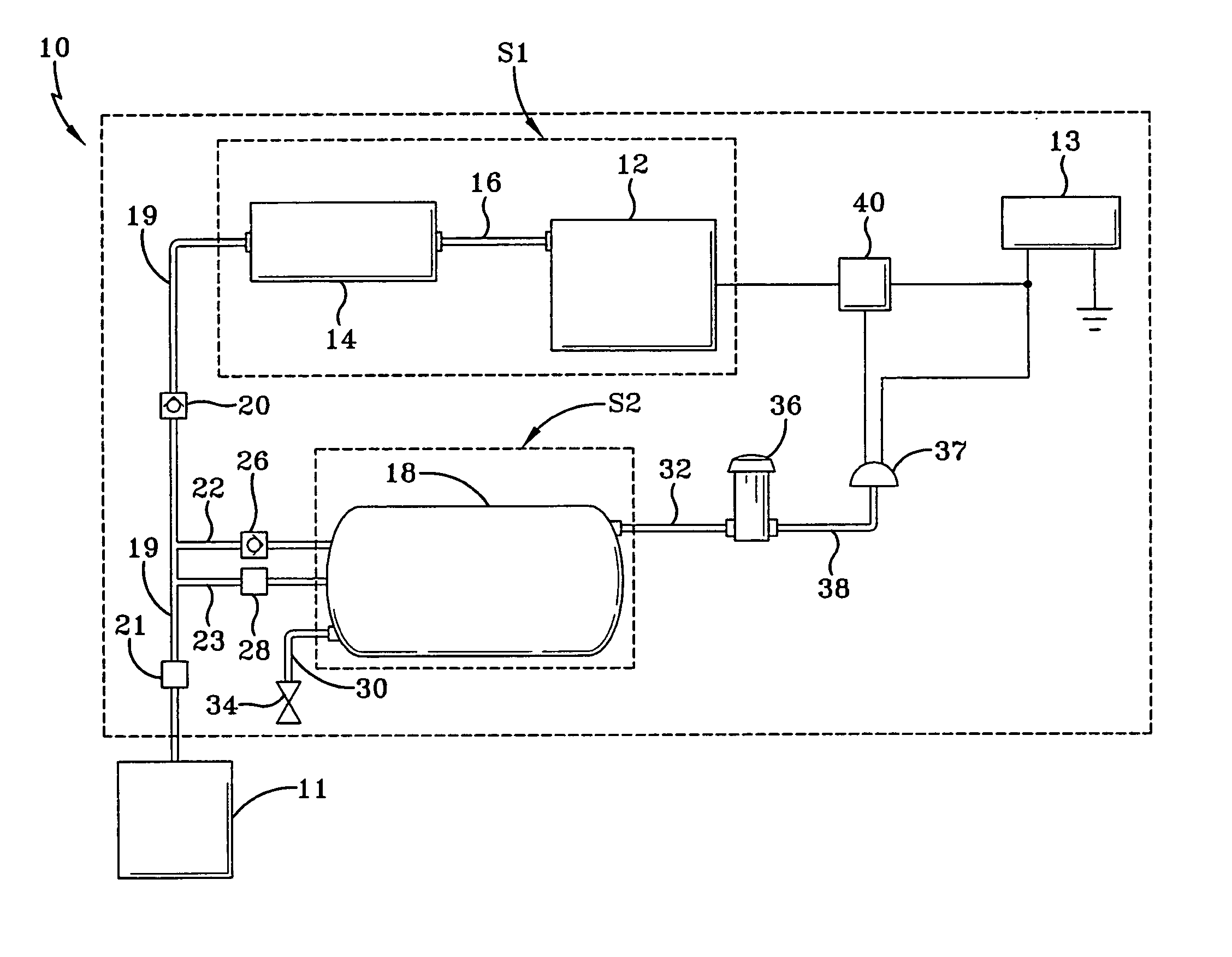
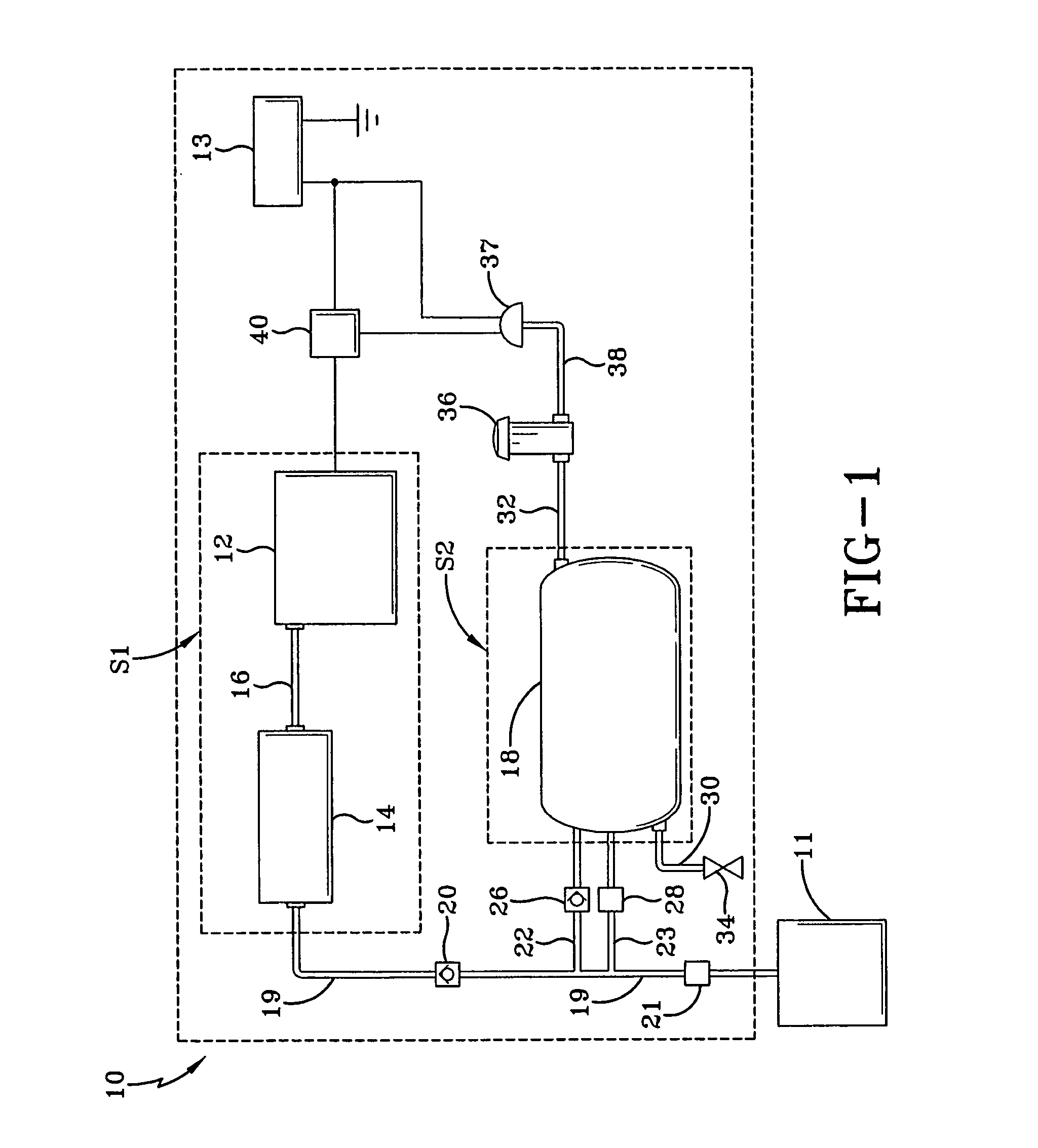
[0011] The charging system of the present invention is generally indicated by the numeral 10 in the accompanying drawings. The charging system 10 can be used to supply dry compressed air to equipment such as a central tire inflation system 11. For example, according to the demands of an operator, the central tire inflation system 11 is used for inflating and deflating tires of vehicles including heavy vehicles such as buses and trucks. To facilitate inflation and deflation of the tires, the central tire inflation system 11 requires the supply of dry compressed air provided by the charging system 10, and, as discussed below, the charging system 10 is capable of supplying dry compressed air from two (2) sources.

[0012] As shown in FIG. 1, the charging system 10 includes an air compressor 12. Operation of the compressor 12 serves to generate compressed air at between 35 and 170 lbs / in2. As those skilled in the art will appreciate, the compressor 12 can be selected from a variety of typ...


PUM


Abstract

A charging system used for supplying compressed air to a destination includes a compressor for generating the compressed air and a reservoir capable of being alternately discharged and recharged with the compressed air. A supply line fluidly connects the compressor, the reservoir, and the destination. A control valve positioned along the supply line is used in controlling flow of the compressed air from the charging system to the destination. A first branch line and a second branch line are positioned between the reservoir and the supply line. A check valve is positioned along the first branch line that when opened allows the compressed air to flow out of the reservoir into the supply line and when closed prohibits the compressed air from flowing into or out of the reservoir. A pressure protection valve is positioned along the second branch that opens to allow the compressed air to flow into the reservoir when the pressure in the supply line is above a threshold pressure.

Description

TECHNICAL FIELD [0001] The present invention is generally related to a charging system for supplying compressed air to a specified destination. More particularly, the present invention is related to a charging system for supplying dry compressed air from a first source, a second source, or both the first and second sources to equipment requiring dry compressed air. More specifically, the present invention is related to a charging system that, when subject to demands of equipment requiring dry compressed air, can supply dry compressed air from both the first and second sources simultaneously. BACKGROUND [0002] Vehicles such as buses and trucks require supplies of compressed air. For example, equipment such as central tire inflation systems used on buses and trucks requires compressed air to inflate and deflate the tires of these vehicles. Previously, compressed air has been supplied to the central tire inflation systems solely from air compressors. However, because of the large deman...

Claims


Application Information

Patent Timeline
IPC IPC(8): B01D53/02
CPCB60C23/003F17C2270/0176F17C2270/0171B60T17/002B60C23/00354B60C23/00372Y10T137/86051
Inventor HOFFMAN, FRED W.
Owner BENDIX COMML VEHICLE SYST LLC
Learn More