Electronic method and system for monitoring distribution facilities

a distribution facility and electronic technology, applied in the field of electronic methods and systems for monitoring distribution facilities, can solve the problems of increasing vehicle transportation costs, complicated and complex operation of the mixing center of a distributed manufacturing enterprise, and reducing the efficiency so as to achieve the effect of determining the financial impact of the mixing center operation

Inactive Publication Date: 2007-09-06
FORD MOTOR CO
View PDF22 Cites 4 Cited by
  • Summary
  • Abstract
  • Description
  • Claims
  • Application Information

AI Technical Summary

Benefits of technology

[0010] One aspect of the present invention is an electronic method and system for monitoring mixing center operations. In certain aspects, the electronic method and system provides an efficient means for tracking performance from an assembly plant to a final destination. Another aspect of the present invention is a method and system for effectively determining the financial impacts of the mixing center operation. According to another aspect, a method and system is provided that generates usable, real-time and accessible information concerning a mixing center system.

Problems solved by technology

A mixing center operation of a distributed manufacturing enterprise is often complicated and intricate.
Each mixing center can present unique challenges based on its geographic location, e.g. its proximity to a manufacturing plant.
For example, inefficient mixing center operations can cause delays in the fulfillment of customer vehicle orders.
Moreover, inefficient systems may result in the increase of vehicle transportation costs.
Current proposals fall short of measuring the impact of carrier performance on the overall performance of the mixing center operation.
However, this metric is difficult to translate into financial terms, for example, the translation of how relatively slow transit times affect the manufacturer costs.
Furthermore, current proposals do not sufficiently address the real time informational needs of automotive manufactures.
Gathering this information commonly takes longer than a day period.
Moreover, obtaining this daily data and / or tracking carrier performance causes delays in the operation of the mixing center system.

Method used


Image

  • Electronic method and system for monitoring distribution facilities
  • Electronic method and system for monitoring distribution facilities
  • Electronic method and system for monitoring distribution facilities

Examples


Embodiment Construction

[0033] As required, detailed embodiments of the present invention are disclosed herein. However, it is to be understood that the disclosed embodiments are merely exemplary of the invention that may be embodied in various and alternative forms. Therefore, specific functional details described herein are not to be interpreted as limiting, but merely as a representative basis for the claims and / or as a representative basis for teaching one of ordinary skill in the art to variously employ the present invention.

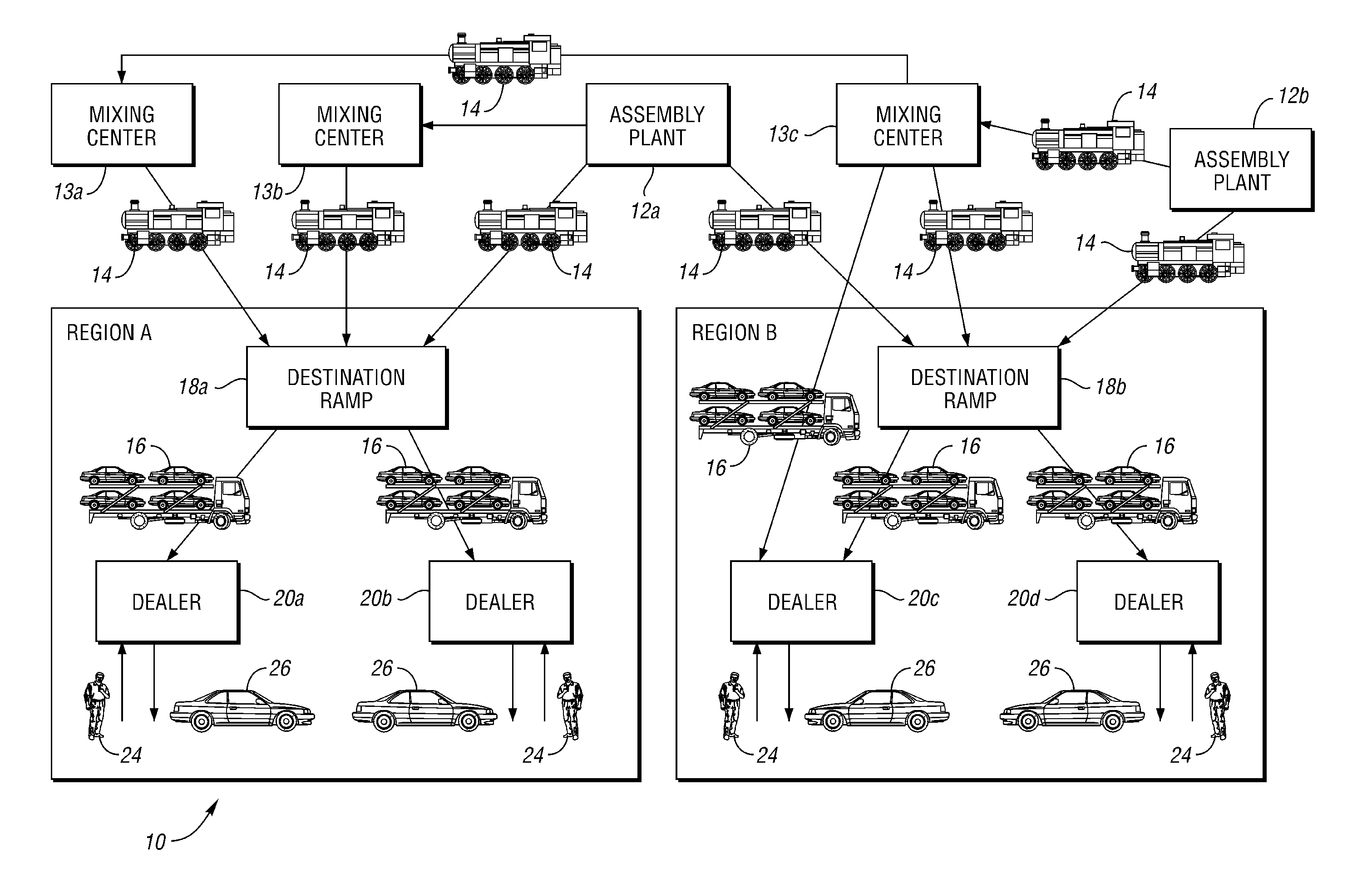
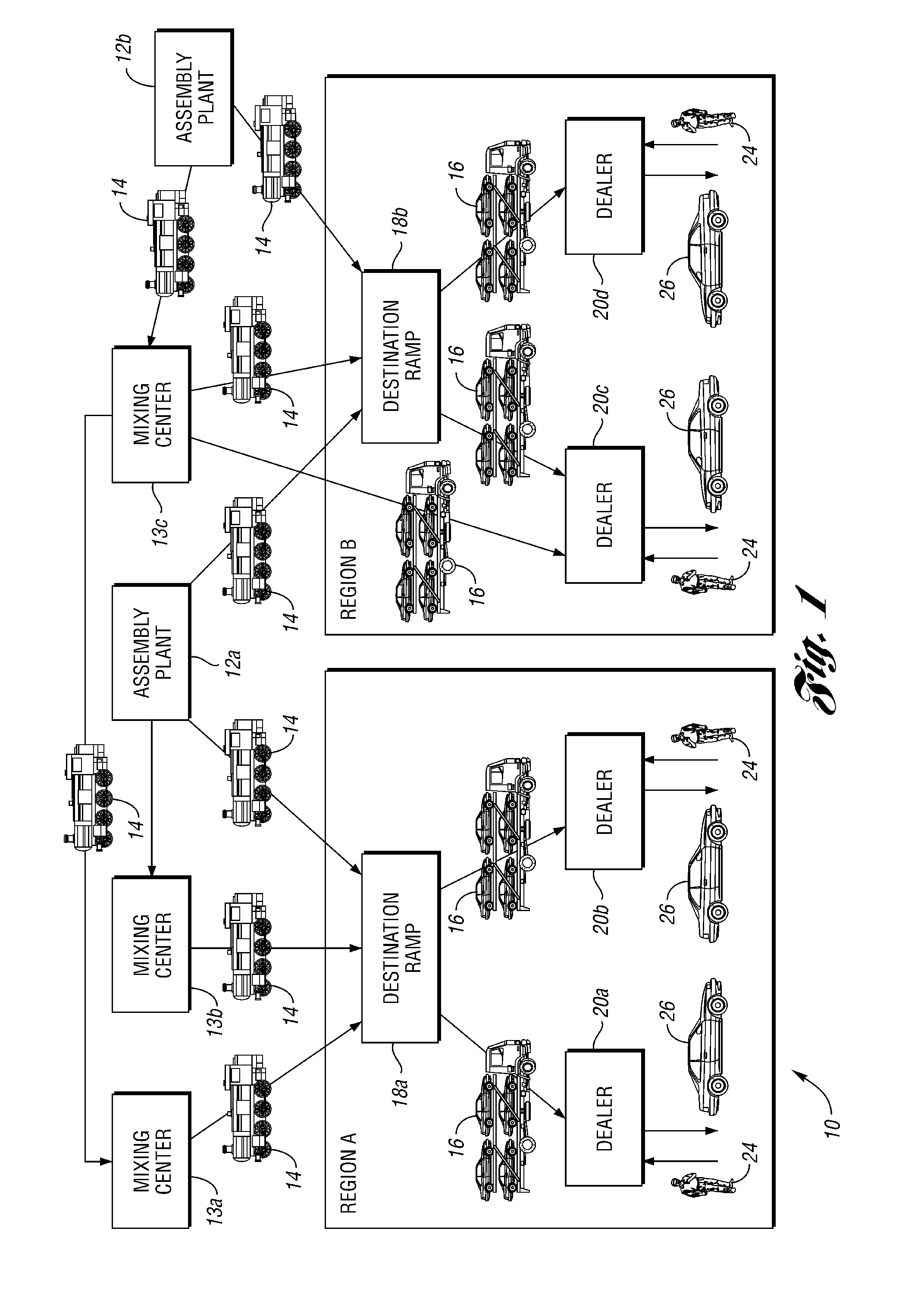
[0034]FIG. 1 depicts a system 10 suitable for implementing one or more embodiments of the present invention. Assembly plants 12a and 12b assemble automotive vehicles 26 for use by vehicle customers 24. Mixing centers 13a, 13b and 13c receive and mix vehicles assembled by assembly plants 12a and 12b. Vehicles 26 exiting each of the assembly plants 12a and 12b and the mixing centers 13a, 13b and 13c can be loaded onto railroad cars 14. It should be understood that shuttles (e.g., a...


PUM


Abstract

An electronic method for monitoring one or more distribution facilities in a manufacturing enterprise which manufactures a number of products for purchase through a number of dealers. The method includes the steps of receiving distribution facility profile information for one or more distribution facilities and daily activity information for the one or more distribution facilities; and calculating a carrying cost for each of the one or more distribution facilities based on the profile and daily activity information. The one or more distribution facilities can be one or more mixing centers.

Description

BACKGROUND OF THE INVENTION [0001] 1. Field of the Invention [0002] One aspect of the present invention generally relates to an electronic method and system for monitoring distribution facilities, and in certain aspects, an electronic method and system for monitoring one or more mixing centers. [0003] 2. Background Art [0004] A mixing center operation of a distributed manufacturing enterprise is often complicated and intricate. Each mixing center can present unique challenges based on its geographic location, e.g. its proximity to a manufacturing plant. [0005] A non-limiting example of a distributed manufacturing enterprise is an automobile manufacturer. In this context, as vehicles (products) depart from assembly plants, the vehicles are sent to mixing centers, which can also serve as destination ramps, via rail, convoy or other transportation devices. From the mixing centers, the vehicles can be shipped to vehicle dealers and / or destination ramps (destinations) situated in geograp...

Claims


Application Information

Patent Timeline
Patent Type & Authority Applications(United States)
IPC IPC(8): G06Q10/00G06Q30/00
CPCG06Q10/063G06Q10/0832G06Q10/08
Inventor SCHILLER, JULIEJOY, ARTHUR
Owner FORD MOTOR CO
Why Eureka
Try Eureka