
Fitting a neural prosthesis using impedance and electrode height

a neural prosthesis and electrode height technology, applied in the field of neural stimulation, can solve the problems of large prosthetic devices, ineffective stimulation of magnitude less than the threshold of perception, and inability to accurately aid the visually impaired, and achieve the effect of quick identification of defective electrodes

Inactive Publication Date: 2007-08-16
DOHENY EYE INST +1
View PDF9 Cites 20 Cited by
  • Summary
  • Abstract
  • Description
  • Claims
  • Application Information

AI Technical Summary

Benefits of technology

[0023] The invention is a method of automatically adjusting an electrode array to the neural characteristics of an individual subject. The response to electrical neural stimulation varies from subject to subject. Measure of impedance may be used to predict the electrode height from the neural tissue and, thereby, predict the threshold of perception. Alternatively, electrode height may be measured directly to predict the threshold of perception. Also, impedance measurement may be used to quickly identify defective electrodes and proper electrode placement.

Problems solved by technology

While some of these early attempts met with some limited success, these early prosthetic devices were large, bulky and could not produce adequate simulated vision to truly aid the visually impaired.
Any stimulation with magnitude less than the threshold of perception is ineffective in producing an image.
Stimulation beyond a maximum level will be painful and possibly dangerous to the subject.
As resolution (number of electrodes) increases, it is tedious or impossible to adjust each electrode by stimulating and eliciting a subject response.
It is unpleasant for a subject to first concentrate to detect the minimum perception and then be subjected to stimulation near the threshold of pain.
One major concern in the field has been that the amount of electrical charge needed to elicit light percepts might be too high to permit long-term stimulation without damage to the retina.
A second concern is that the current required to elicit percepts may fluctuate over time, due to either neurophysiological change or damage to the retina itself, electrochemical changes on the electrode surface, or instability of position of the array on the retinal surface.
One likely explanation for these high thresholds is that it is extremely difficult to lay an electrode array flush on the retinal surface during an acute trial.

Method used


Image

  • Fitting a neural prosthesis using impedance and electrode height
  • Fitting a neural prosthesis using impedance and electrode height
  • Fitting a neural prosthesis using impedance and electrode height

Examples


Embodiment Construction

[0037] The following description is of the best mode presently contemplated for carrying out the invention. This description is not to be taken in a limiting sense, but is made merely for the purpose of describing the general principles of the invention. The scope of the invention should be determined with reference to the claims.

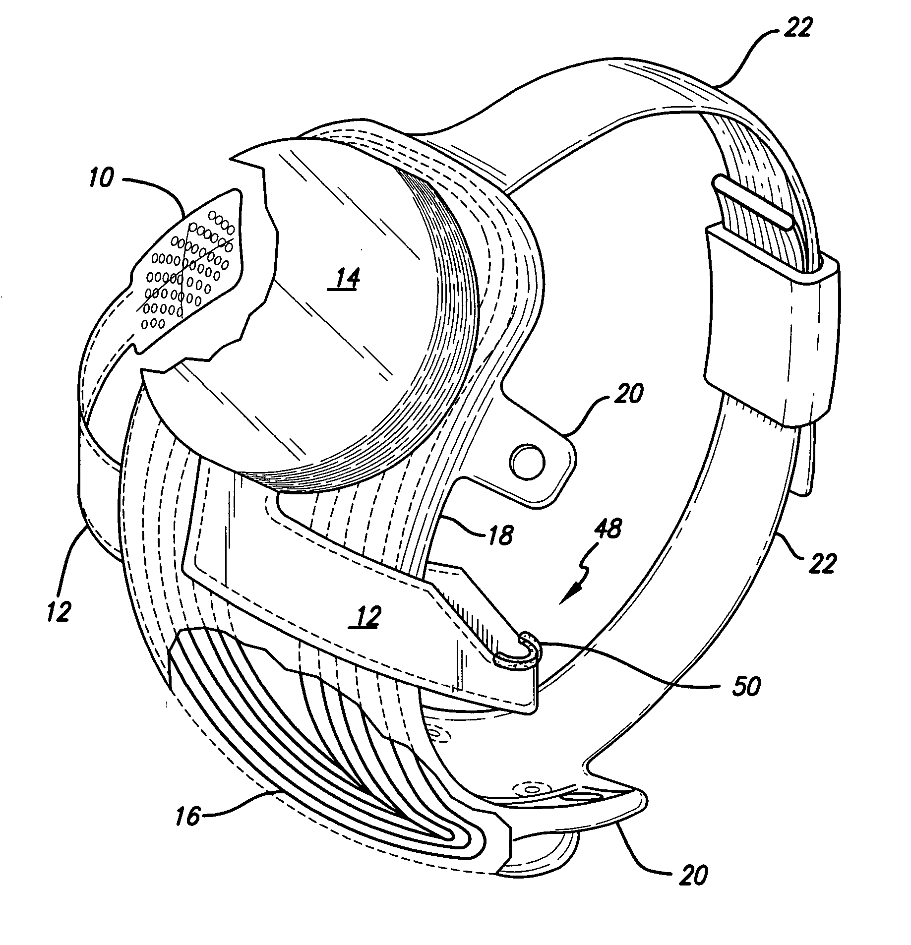
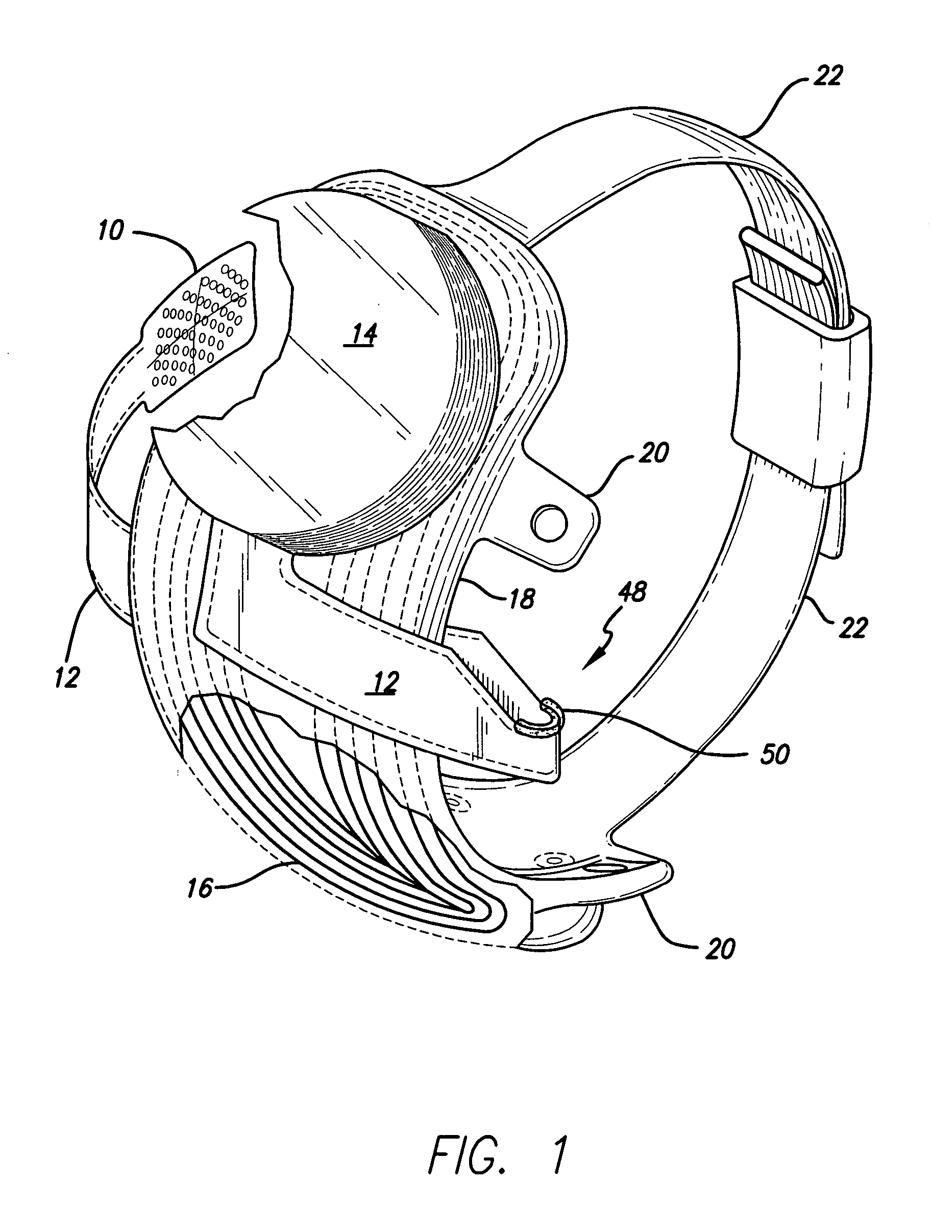
[0038]FIG. 1 shows a perspective view of the implanted portion of the preferred retinal prosthesis. A flexible circuit 1 includes a flexible circuit electrode array 10 which is mounted by a retinal tack (not shown) or similar means to the epiretinal surface. The flexible circuit electrode array 10 is electrically coupled by a flexible circuit cable 12, which pierces the sclera and is electrically coupled to an electronics package 14, external to the sclera.

[0039] The electronics package 14 is electrically coupled to a secondary inductive coil 16. Preferably the secondary inductive coil 16 is made from wound wire. Alternatively, the secondary inductive coi...


PUM


Abstract

The invention is a method of automatically adjusting an electrode array to the neural characteristics of an individual subject. The response to electrical neural stimulation varies from subject to subject. Measure of impedance may be used to predict the electrode height from the neural tissue and, thereby, predict the threshold of perception. Alternatively, electrode height may be measured directly to predict the threshold of perception. Also, impedance measurement may be used to quickly identify defective electrodes and proper electrode placement.

Description

CROSS REFERENCE TO RELATED APPLICATIONS [0001] This application claims priority to U.S. Provisional Patent Application 60 / 741,810, filed Dec. 1, 2005, for Correlation of Electrode Height, Stimulation Threshold and Impedance in a Retinal Prosthetic Implant, and 60 / 853,477, filed Oct. 20, 2006, for Real Time Electrode Impedance Measurement and Data Display for an Implantable Device. This application is related to and incorporates herein by reference, U.S. patent application Ser. Nos. 10 / 864,590, filed Jun. 8, 2004, for Automatic Fitting for a Visual Prosthesis, and 11 / 357,680, filed Feb. 16, 2006, for Fitting of Brightness in a Visual Prosthesis.GOVERNMENT RIGHTS NOTICE [0002] This invention was made with government support under grant No. R24EY12893-01, awarded by the National Institutes of Health. The government has certain rights in the invention.FIELD OF THE INVENTION [0003] The present invention is generally directed to neural stimulation and more specifically to an improved meth...

Claims


Application Information

Patent Timeline
IPC IPC(8): A61N1/18
CPCA61N1/0543A61N1/37247A61N1/36046
Inventor GREENBERG, ROBERT J.FINE, IONEROY, ARUPMCMAHON, MATTHEW J.HUMAYUN, MARK S.WEILAND, JAMES DAVIDHORSAGER, ALAN M.ZHOU, DAO MINHINES, AMYYADAV, SUMITDAI, RONGQING
Owner DOHENY EYE INST
Learn More