
Self-propelled endoscopic device

a self-propelled, endoscopic technology, applied in the field of medical devices, can solve the problems of reducing the actual space available, affecting the efficiency of the device's locomotion, and affecting the progress of the device through the intestines, so as to achieve the same degree of flexibility, hinder the device's locomotion efficiency during use, and achieve the effect of reducing the efficiency of the devi

Active Publication Date: 2007-08-02
ERA ENDOSCOPY
View PDF6 Cites 34 Cited by
  • Summary
  • Abstract
  • Description
  • Claims
  • Application Information

AI Technical Summary

Benefits of technology

[0009] Accordingly, it is an object of the present invention to provide a self-propelled endoscopic device that provides the same degree of flexibility as conventional autonomous or semi-autonomous endoscopic devices, but without hindering the device's efficiency of locomotion during use.
[0010] A particular object of the present invention is to provide an endoscopic device of the above-mentioned type wherein the tubular body has a considerable capacity for extension and a low friction coefficient so as to avoid any entrainment of the tissues forming the wall of the body cavity and thus ensure an effective locomotion of the device.
[0011] Another particular object of the present invention is to provide an endoscopic device of the aforementioned type with a significantly more spacious interior, while maintaining the same outer diameter, than is available in endoscopic devices of known type with bellows-shaped bodies, thereby enabling said interior to be used more efficiently for the passage of the service tubes.
[0012] A further object of the present invention is to provide an endoscopic device of the above-mentioned type, wherein its tubular body, or the actuators of the anchoring means provided on its front and rear end portions, will contract without giving rise to any circumferential surface folds in which the tissue of the wall forming the body cavity through which the endoscopic device is advancing might become trapped.

Problems solved by technology

Although it has the considerable flexibility needed to negotiate the narrow intestinal loops without causing pain, the device according to the above-mentioned PCT patent application has several functional drawbacks due to its relative extendibility and friction between its outer surface and the walls of the body cavity, which have a negative effect on the device's efficiency of locomotion.
Though it does no damage the mucosa, this interferes with the progress of the device through the intestines.
It should be noted, moreover, that the considerable thickness of the bellows-shaped tubular body (in terms of the difference between the maximum radius and the minimum radius of the contracted and extended bellows) results in a significant reduction in the space actually available inside it, making difficult the passage of the compressed air tubes needed for the displacement of the device and making it necessary to use smaller-diameter tubes, with a consequent increase in the pressure drop and reduction in the device's speed of locomotion.

Method used


Image

  • Self-propelled endoscopic device
  • Self-propelled endoscopic device
  • Self-propelled endoscopic device

Examples


Embodiment Construction

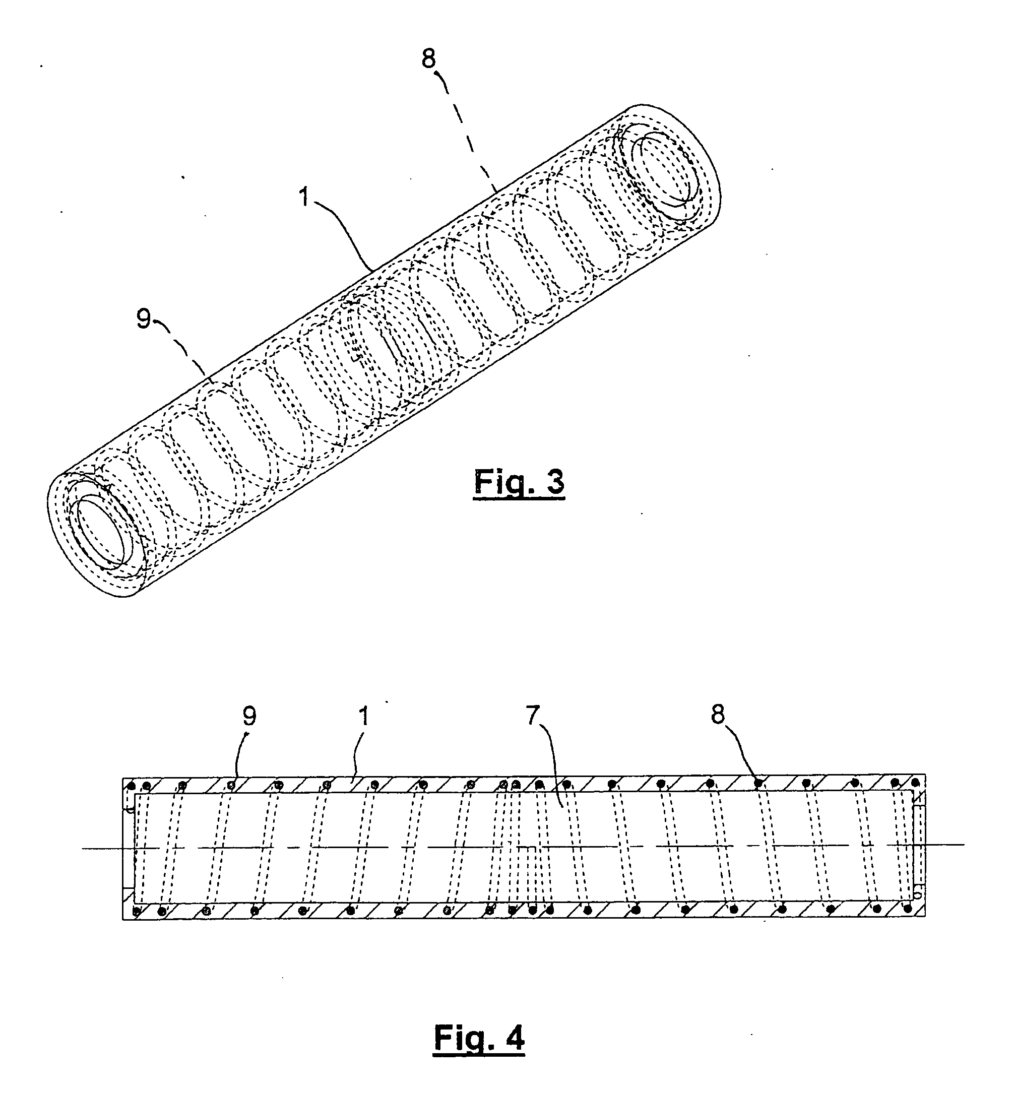
[0021] Referring now to the drawings and, more particularly, to FIGS. 1-6, there is shown generally a self-propelled endoscopic device, in accordance with various aspects of the present invention. According to one embodiment, as set forth in FIG. 1, the device comprises a tubular body 1 extending between two end portions, referred to generally as front 2 and rear 3 end portions, respectively, the terms front and rear referring to the device's direction of locomotion through a selected body cavity, as indicated generally by arrow F. In this manner, the device is preferably and advantageously moveable in both forward and reverse directions within the body cavity.

[0022] The front 2 and rear 3 end portions of the device include anchoring means 4, specifically of the clamping type, by means of which the device temporarily and alternately becomes attached to the wall of the body cavity to enable its locomotion in a known manner.

[0023] According to the present invention, the tubular body...


PUM


Abstract

An endoscopic device for autonomous locomotion through a body cavity with a predetermined direction, the device comprising a tubular body constructed of a relatively elastic material that extends between two, preferably, the front and rear, end portions, respectively. The tubular body includes an anchor for temporarily and alternately attaching the end portions to a wall portion of the body cavity in synch with corresponding axial extensions and contractions of the tubular body. The tubular body incorporates a reinforcement structure distributed along its length that is substantially rigid in a radial direction and yields in an axial direction, the structure specifically comprising either a plurality of relatively rigid rings or at least one helical spring.

Description

FIELD OF THE INVENTION [0001] The present invention relates generally to medical devices and, more particularly, to a device suitable for locomotion through a body cavity. BACKGROUND OF THE INVENTION [0002] Endoscopic devices are typically used by surgeons for a variety of surgical and / or diagnostic procedures. In operation, a surgeon applies manual force, for instance, directly to the device in order to impart forward motion of the device through a patient's body. Such devices are usually operated in conjunction with other surgical and / or diagnostic instruments, e.g., micro-arms, micro-cameras and / or laser emitters, that may be needed to complete various medical procedures. [0003] Endoscopic devices for surgical or diagnostic procedures are already known, which are operated by the surgeon who directly imparts to the device its forward motion through the patient's body. These devices are generally associated with surgical and / or diagnostic instruments needed to complete various proc...

Claims


Application Information

Patent Timeline
IPC IPC(8): A61B1/00
CPCA61B1/00094A61M25/0116A61B1/31A61B1/00156A61B1/012A61B1/00
Inventor GORINI, SAMUELEARENA, ALBERTOPEMORIO, GIUSEPPEMENCIASSI, ARIANNADARIO, PAOLO
Owner ERA ENDOSCOPY
Learn More