Radio communication system
a communication system and radio technology, applied in the field of radio communication systems, can solve the problems of increasing power consumption, deteriorating amplifier efficiency, complicated apparatus configuration and control, etc., and achieve the effect of reducing the peak of transmission power, reducing the papr, and reducing the operating poin
- Summary
- Abstract
- Description
- Claims
- Application Information
AI Technical Summary
Benefits of technology
Problems solved by technology
Method used
Image
Examples
first embodiment
[0083] In this embodiment, a radio format used at the time of connection setup is specified from a radio network controller (RNC) controlling a radio communication channel to a base transceiver station BTS by a terminal MS attempting to connect to the base transceiver station BTS under the control of the radio network controller (RNC).
[0084] Description will be made of the process thereof.
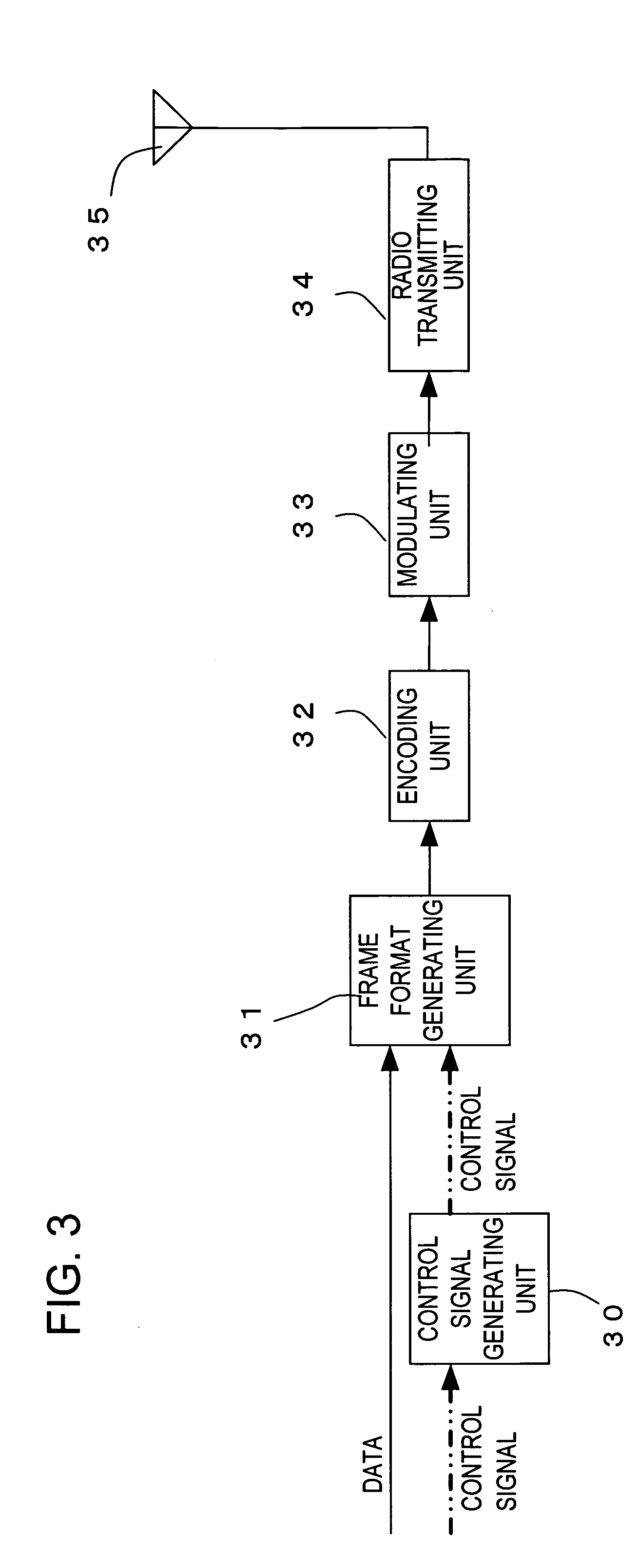
[0085]FIG. 9 is a block diagram of a configuration example of the base transceiver station BTS in an OFDM system according to a first embodiment. FIG. 11 is a block diagram of a configuration example of the terminal MS connecting to the base transceiver station BTS.
[0086]FIG. 10 is a block diagram of a configuration example of a frame format controlling unit 36 of FIG. 9. FIG. 12 is a process sequence flowchart corresponding to the first embodiment.
[0087] An OFDMA system capable of four-user-multiplexing is taken as an example. The radio formats used in this case are assumed to be four types F1...
second embodiment
[0110] Although the radio network controller RNC selects the utilized frame format and notifies the base transceiver station BTS of the format in the first embodiment, the base transceiver station BTS performs the selection in a second embodiment.
[0111]FIG. 14 is a process sequence flowchart according to the second embodiment.
[0112] A connection setting request for one terminal MS is notified from the radio network controller RNC to the base transceiver station BTS (step S1). As described in FIG. 13, the base transceiver station BTS selects the utilized format from the frame formats that can be selected such that the peak transmission power is reduced after the user-multiplexing (step S2a). The result is notified to the terminal MS (step S3).
[0113] Subsequently, the processes same as the first embodiment (steps S4, S5) are performed for the communication (step S6). The selected frame format is used until the phone call is terminated. In this way, the same effects as the first emb...
third embodiment
[0115] As is the case with the first and second embodiments, the utilized frame format is selected in the base transceiver station BTS when setting the connection. In consideration of the frame formats used by other connecting terminals MS, the utilized frame format is subsequently changed such that the transmission power peak is reduced.
[0116] It is assumed that a terminal MS selects the utilized frame format when setting the connection as is the case with the first and second embodiments and performs the communication. A connection request is assume to be notified from another terminal MS1 that is using the frame format 3 because of handover, etc. However, it is assumed that yet another terminal MS2 is using the frame format 3 and the frame format 1 is not used.
[0117] In this case, to constrain the overall transmission power peak in the base transceiver station, it is desirable that the terminal MS1 uses the frame format 1. Therefore, The utilized frame format of the terminal MS...
PUM
 Abstract
Description
Claims
Application Information
 - R&D
- Intellectual Property
- Life Sciences
- Materials
- Tech Scout
- Unparalleled Data Quality
- Higher Quality Content
- 60% Fewer Hallucinations
Browse by: Latest US Patents, China's latest patents, Technical Efficacy Thesaurus, Application Domain, Technology Topic, Popular Technical Reports.
© 2025 PatSnap. All rights reserved.Legal|Privacy policy|Modern Slavery Act Transparency Statement|Sitemap|About US| Contact US: help@patsnap.com


