Weld wire with large cast, method of making same, and loaded spool article of manufacture

Inactive Publication Date: 2007-08-02
LINCOLN GLOBAL INC
View PDF21 Cites 3 Cited by
  • Summary
  • Abstract
  • Description
  • Claims
  • Application Information

AI Technical Summary

Benefits of technology

[0008] The use of weld wire with a shape memory having a large cast is a deviation from prior common industry practices that teach that weld wire that is fed into a welding machine should have either little or no shape memory or, if shape memory is provided, that the cast imparted into the wire should be small and that a reverse twist process should be used to cause controlled weld wire rotation during its payout. Heretofore, the common practice in the industry was to “kill” the wire to remove the shape memory of the wire prior to winding the weld wire onto a reel, spool, container, or the like or to effect a reverse twist in weld wire having a small cast after it is payed off from a holding spool. It was commonly believed that a weld Wire having a shape memory would adversely affect the unwinding of the weld wire from the reel, spool, container, or the like during the welding process and would further be more susceptible to kinks, bends and other problems as the weld wire is fed through the welder during the welding process. Furthermore, it was commonly believed that a weld wire with shape memory would aggravate the problem associated with consistent weld bead placement. Surprisingly, the use of a shape memory weld wire having a large cast in accordance with the present invention results in the formation of a weld bead having better consistent placement during the welding operation and the formation of higher quality weld beads than weld beads formed by “killed” weld wires. The use of a weld wire with such shape memory defining a large cast has also been found to form a more robust weld bead during the welding process. Furthermore, the use of a weld wire with such shape memory has been found to reduce the occurrence of bends and kinks in the welding wire as it is being used during the welding process such as during the feeding of the weld wire through a welding machine during the welding process.
[0023] It is yet a further and / or alternative -object of the present invention to provide a weld wire which can be successfully used in robotic welding to obtain consistent placement of the weld bead onto a predefined path on a workpiece.

Problems solved by technology

It was commonly believed that a weld Wire having a shape memory would adversely affect the unwinding of the weld wire from the reel, spool, container, or the like during the welding process and would further be more susceptible to kinks, bends and other problems as the weld wire is fed through the welder during the welding process.

Method used


Image

  • Weld wire with large cast, method of making same, and loaded spool article of manufacture
  • Weld wire with large cast, method of making same, and loaded spool article of manufacture
  • Weld wire with large cast, method of making same, and loaded spool article of manufacture

Examples


Embodiment Construction

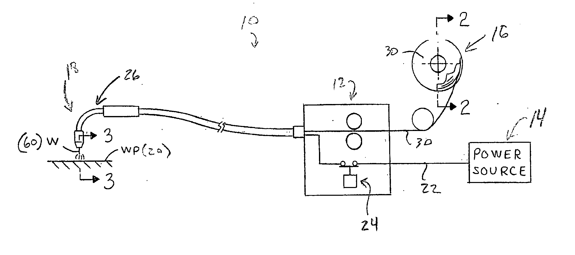
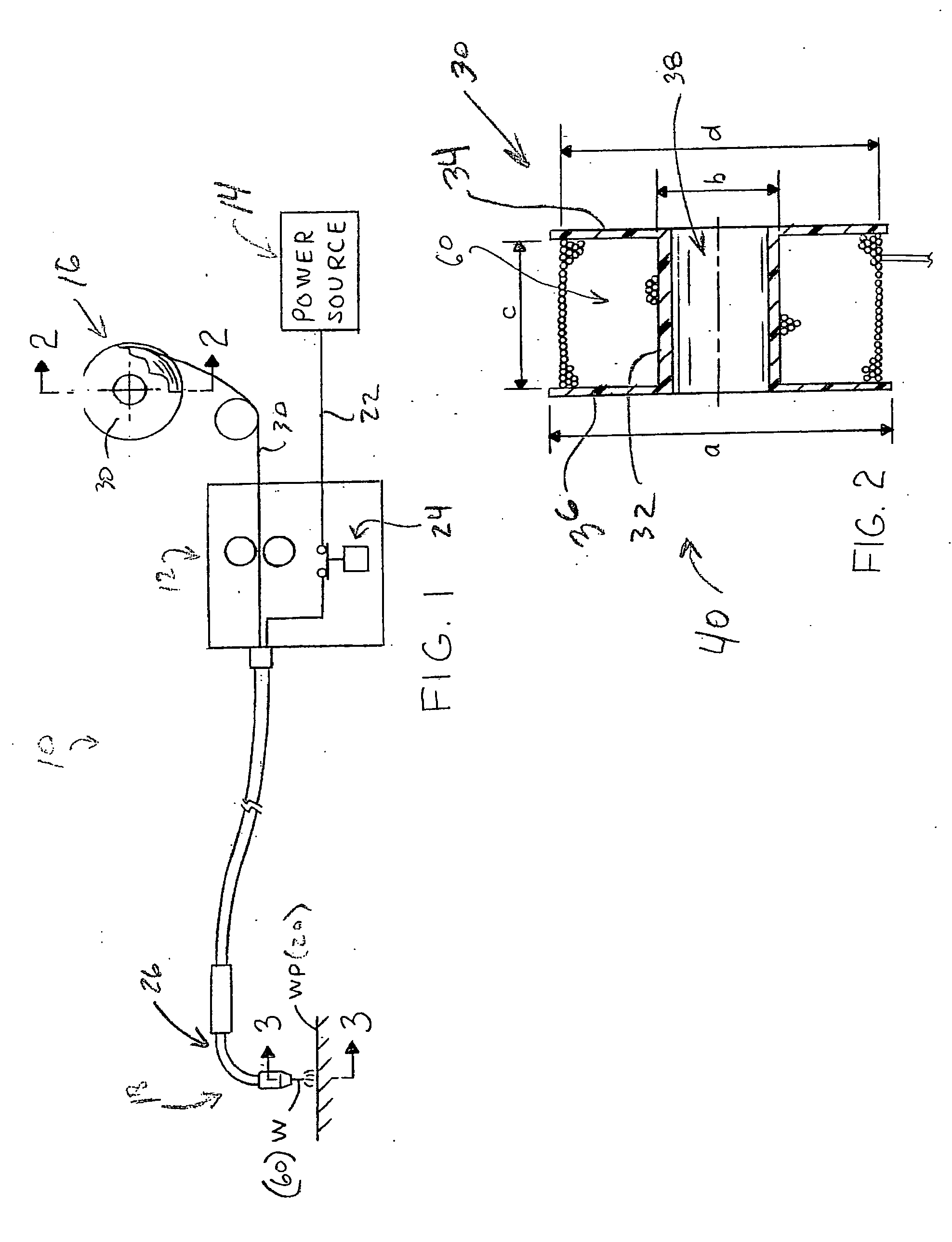
[0045] Referring now to the drawings wherein the showings are for the purposes of illustrating the preferred embodiments only and not for the purpose of limiting same, FIG. 1 is a schematic illustration of an arc welding system 10 into which the preferred embodiments of the present invention find particular application. As shown there, the system 10 includes a control portion 12, a power source 14 for supplying electrical power to the control portion 12, a weld wire storage portion 16 for storing weld wire for payout as needed through the control portion 12 and towards a working portion 18 of the system 10 for forming a weld joint in an associated workpiece 20. The power source 14 is connected with the control portion 12 using suitable electrical lead wires 22 and the like in a manner well known in the art. A switch 24 is illustrated schematically for selectively connecting and disconnecting electrical power for flow between the power source 14 and the working portion 18. A return e...


PUM


Abstract

A weld wire for storage on a spool of weld wire, a method for making same, and an article of manufacture including a weld wire carried on a spool. The weld wire has a substantially linear cast in the form of an undulating curve including a succession of generally semi-circular sections having a generally fixed mean average radius of curvature of about 200 inches but not less than 80 inches. In one form, the cast has a radius of curvature in the range of about 100-300 inches. The linear cast is formed on the weld wire prior to the weld wire being wound onto the spool of weld wire. The linear cast is at least partially retained on the weld wire after the weld wire is unwound from the spool and during the feeding of the weld wire through a welding machine. The spool includes a hub portion having a diameter in the range of about 18-20 inches for carrying weld wire having a diameter in the range of about 0.035-0.062 inches. The present application pertains to the art of welding, and more particularly to welding wires used in welding machines.

Description

BACKGROUND [0001] One of the lingering problems in the field of welding is the consistent formation and placement of a quality weld bead. Various measures have been employed to achieve this goal. For instance, the waveform of the welding current has been closely controlled to achieve better weld bead formation and weld bead quality. In addition, the feed rate of a weld wire has been controlled to produce a higher quality weld bead. The composition of the consumable weld wire and various types of shielding gases used during the welding process have also been employed to achieve higher quality weld beads. Although many of these techniques have significantly improved weld bead quality, consistent weld bead placement on a workpiece has remained illusive. [0002] A remaining problem with obtaining a consistent weld bead placement on a workpiece, however, is the position of the weld wire relative to the workpiece as the weld bead is being formed. It has been found that when the position of...

Claims


Application Information

Patent Timeline
IPC IPC(8): B23K35/02
CPCB23K35/02
Inventor BARTON, DAVID J.COOPER, WILLIAM D.
Owner LINCOLN GLOBAL INC
Why Eureka
Try Eureka