
Combined flexible and rigid intubating video laryngoscope

Inactive Publication Date: 2007-07-26
UNIVERSITY OF ROCHESTER
View PDF8 Cites 23 Cited by
  • Summary
  • Abstract
  • Description
  • Claims
  • Application Information

AI Technical Summary

Benefits of technology

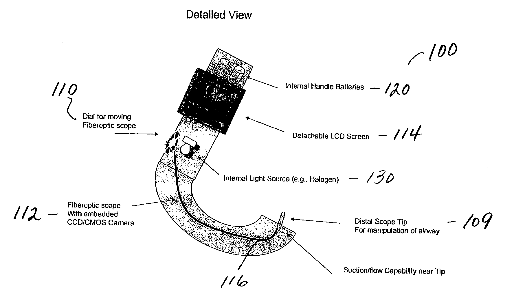
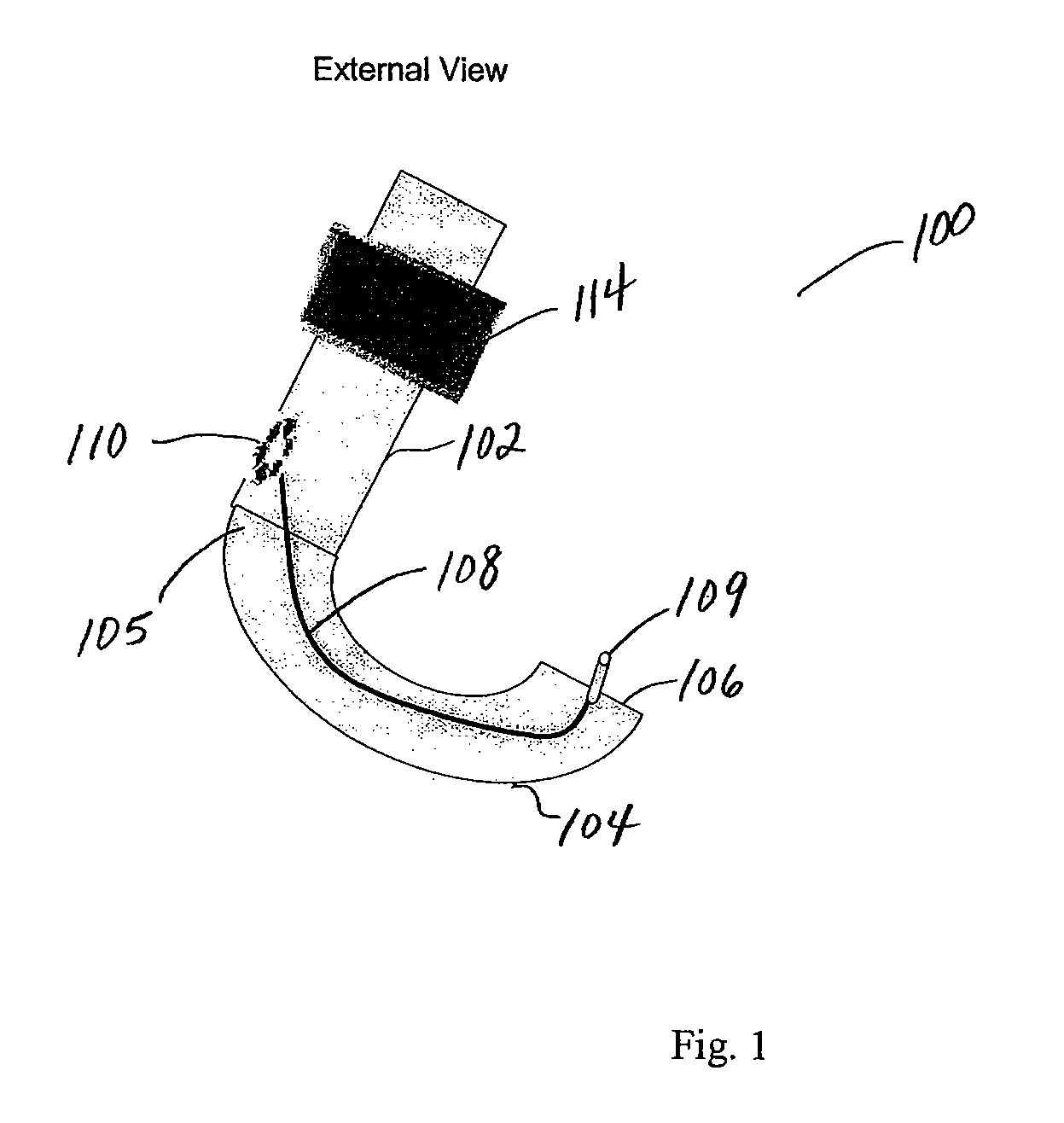
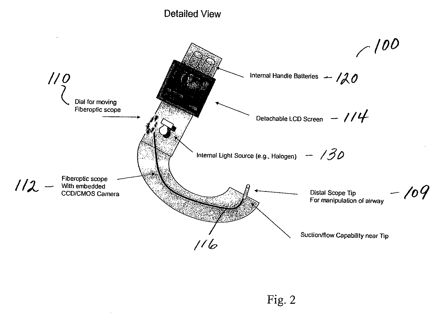
[0010] The present invention provides a combined flexible and rigid intubating video laryngoscope. The laryngoscope has a handle, and a rigid blade, having a proximal end connectible to the handle and a distal end projecting therefrom. The laryngoscope also has a flexible video endoscope having a distal end connectible near the distal end of the blade, the distal end of the endoscope being movable relative to the distal end of the blade, so as to enable the endoscope to obtain a variable view including a more anterior anatomical view of a patient's vocal cords during direct laryngoscopy.

Problems solved by technology

This technique can only be employed if the patient is comatose (unconscious) or under general anesthesia.
However, use of such fiberoptic and / or video laryngoscopes still does not address the chronic problems that are associated with not being able to visualize a desired part of the larynx, since these devices still don't allow for a good visualization of the vocal chords.
While anatomical variation, often assigned various classifications, determines the potential for a “best view” of the vocal chords, this perspective is not always optimal.
Physician skill variation can determine the extent of a “best view,” but in many patients with suboptimal anatomy this view has serious limitations.
Prior art enhanced laryngoscopes may have improved how a physician views the larynx, yet these devices do not give physicians the ability to change their view of the larynx at the point of intubation.
For example, while fiberoptic technologies exist to allow for changes in the view, such techniques are cumbersome and often are used in only the worst patients.
One can not freely intubate patients with the non-scope hand using fiberoptic technologies, making it impractical for common use.
Based in part on experience in otolaryngology where physicians are often called for the worst airways, the single “best view” of these scopes often leads to lost airways and patient complications.
This view invariably is too far posterior, not allowing for good visualization of the vocal chords, and thus subsequently complicating intubation.

Method used


Image

  • Combined flexible and rigid intubating video laryngoscope
  • Combined flexible and rigid intubating video laryngoscope
  • Combined flexible and rigid intubating video laryngoscope

Examples


Embodiment Construction

[0023] The embodiments of the present invention provide a combined flexible and rigid intubating laryngoscope that includes several novel features. A first novel feature is directed towards the use of a small display screen, such as a liquid quartz display (LCD) screen that is removably attached to the scope. The display screen is similar to those found on commercially available video cameras. With the small display screen, the line of sight can be upward, without excess wires leading to a non-attached video screen, such as those used with video or other video-based laryngoscopes or endoscopes. This screen can be detached to allow for the scope to be cleaned between intubations. The screen is operatively connected with an imaging device (e.g., a CCD camera) at the end of the fiberoptic scope.

[0024] A second novel feature is related to the laryngoscope's a rigid and curved blade. Integrated into the tip of the blade section of the laryngoscope in accordance with the embodiments of t...


PUM


Abstract

A combined flexible and rigid intubating video laryngoscope. The laryngoscope has a handle, and a rigid blade, having a proximal end connectible to the handle and a distal end projecting therefrom. The laryngoscope also has a flexible video endoscope having a distal end connectible near the distal end of the blade, the distal end of the endoscope being movable relative to the distal end of the blade, so as to enable the endoscope to obtain a variable view including a more anterior anatomical view of a patient's vocal cords during direct laryngoscopy.

Description

CROSS-REFERENCES TO RELATED APPLICATIONS [0001] This application claims priority to U.S. Provisional Patent Application No. 60 / 709,189, filed Aug. 17, 2005, the disclosure of which is hereby incorporated by reference in its entirety for all purposes.BACKGROUND OF THE INVENTION [0002] The present invention relates generally to a laryngoscope, and more particularly to a combined flexible and rigid intubating laryngoscope. [0003] A laryngoscope is a medical instrument for examining the larynx. The larynx is a cartilaginous structure at the top of the trachea that contains elastic vocal cords that are the source of the vocal tone in speech. The trachea is a membranous tube with cartilaginous rings that conveys inhaled air from the larynx to the bronchi. A laryngoscope is used to obtain a view of the glottis (i.e., the vocal apparatus of the larynx, consisting of the true vocal cords and the opening between them) by direct laryngoscopy. A standard adult laryngoscope consists of a handle ...

Claims


Application Information

Patent Timeline
IPC IPC(8): A61B1/267
CPCA61B1/2673
Inventor DUTCHER, PAULTAGHIZADEH, FARHAN
Owner UNIVERSITY OF ROCHESTER
Learn More