
Osteochondral implant procedure

a technology of osteochondral implants and implants, which is applied in the field of osteochondral implant procedures, can solve the problems of poor healing of tearing, swelling and limited motion, and less than optimal healing

Active Publication Date: 2007-07-26
WARSAW ORTHOPEDIC INC
View PDF13 Cites 35 Cited by
  • Summary
  • Abstract
  • Description
  • Claims
  • Application Information

AI Technical Summary

Problems solved by technology

This tearing does not heal well due to the lack of nerves, blood vessels and lymphatic systems; and the resultant knee pain, swelling and limited motion of the bone(s) must be addressed.
Damaged cartilages have historically been treated by a variety of surgical interventions including lavage, arthroscopic debridement, and repair stimulation, all of which provide less than optimum results.
However, the known artificial prostheses have largely been unsuccessful since they are deficient in the elastic, and therefore in the shock-absorbing, properties characteristic of the cartilage.
Moreover, the known artificial devices have not proven able to withstand the forces inherent to routine knee joint function.
Since the geometry of the defect is often complex, it is often difficult to perfectly match the dimensions of the grafts(s) to those of the openings(s).
Also, in the case of relatively large defects requiring multiple grafts, it is often difficult to determine, in advance of harvesting, the size and number of grafts that are needed.

Method used


Image

  • Osteochondral implant procedure
  • Osteochondral implant procedure
  • Osteochondral implant procedure

Examples


Embodiment Construction

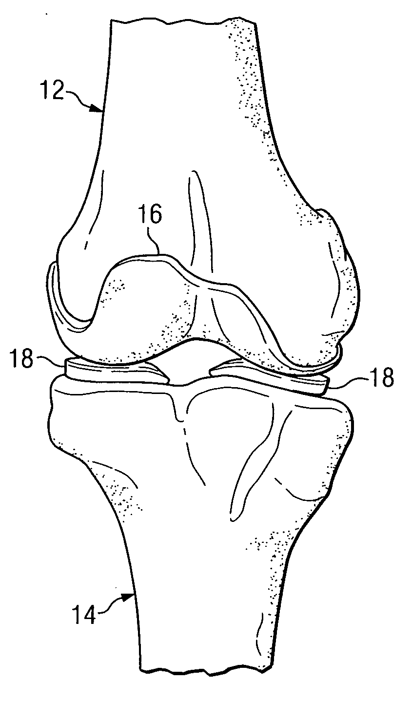
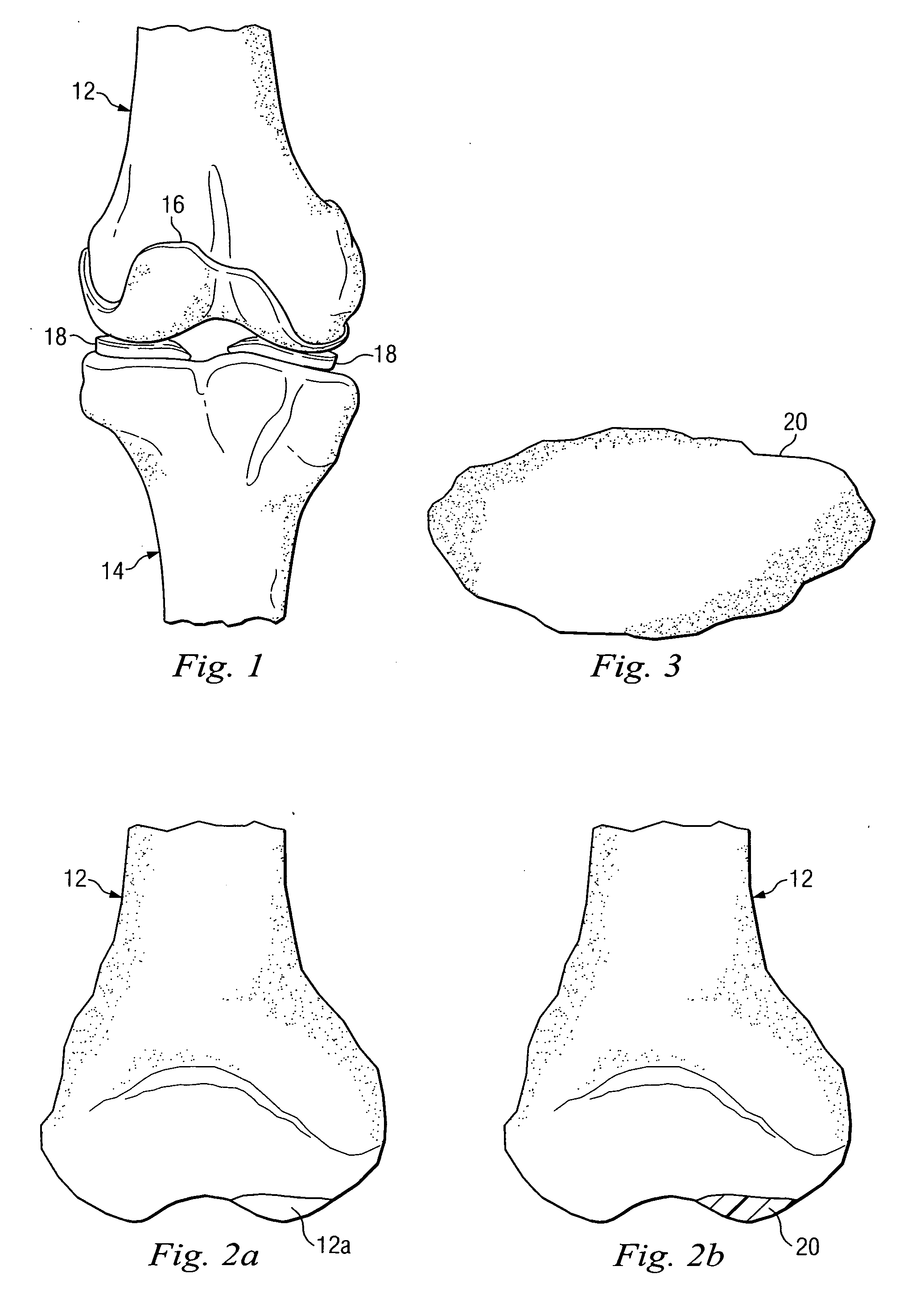
[0015] Referring to FIG. 1 of the drawing, the reference numeral 10 refers, in general, to a knee area of a human including a femur 12 and a tibia 14 whose respective chondral areas are in close proximity. A cartilage 16 extends over a portion of the chondral area of the femur 12, and a meniscus 18 extends between the cartilage and the tibia 14. The patella, as well as the tendons, ligaments, and quadriceps that also form part of the knee are not shown in the interest of clarity.

[0016]FIG. 2a depicts a defect, or void, 12a in the femur 12 of FIG. 1. In this context, it will be assumed that at least a portion of the defect 12a was created as a result of a portion of the cartilage 16 extending over a chrondral area of the femur 12 wearing away or becoming damaged and being removed by the surgeon. It also will be assumed that the defect 12a also includes a portion of the condyle that extended immediately below the worn or removed cartilage.

[0017] According to an embodiment of the pro...


PUM


Abstract

A surgical procedure for preparing a damaged area of a human knee to receive at least one graft, according to which a moldable material is positioned over the damaged area and removed after it hardens. The mold is used as a template to determine the number and / or a dimension of the openings to be formed in the damaged area for receiving corresponding grafts.

Description

BACKGROUND [0001] This invention relates to an improved osteochondral implant procedure, and more particularly, to such a procedure in which one or more recipient openings are form in the anatomy for receiving a graft. [0002] In the human body, the knee consists of three bones—a femur, a tibia, and a patella—that are held in place by various ligaments. The corresponding chondral areas of the femur and the tibia form a hinge joint, and the patella protects the joint. Portions of the chrodral areas, as well as the underside of the patella, are covered with an articular cartilage, which allow the femur and the tibia to smoothly glide against each other without causing damage. [0003] The articular cartilage often tears, usually due to traumatic injury (often seen in athletics) and degenerative processes (seen in older patients). This tearing does not heal well due to the lack of nerves, blood vessels and lymphatic systems; and the resultant knee pain, swelling and limited motion of the ...

Claims


Application Information

Patent Timeline
IPC IPC(8): A61F13/00
CPCA61F2/30756A61F2250/0039A61F2/4684A61F2002/2835A61F2002/2839A61F2002/30113A61F2002/30327A61F2002/30616A61F2002/30759A61F2002/30957A61F2002/3096A61F2002/30963A61F2002/4649A61F2230/0006A61F2/3859Y10S623/906
Inventor NYCZ, JEFFREY H.SHIMKO, DANIELBHARADWAJ, JEETENDRA
Owner WARSAW ORTHOPEDIC INC
Learn More