Fluorescent conversion medium and color light emitting device

Inactive Publication Date: 2007-07-19
IDEMITSU KOSAN CO LTD
View PDF5 Cites 47 Cited by
  • Summary
  • Abstract
  • Description
  • Claims
  • Application Information

AI Technical Summary

Benefits of technology

[0016] A semiconductor material represented by CdSe exhibits a refractive index as high as about 2.5 to 4 in the visible region. On the other hand, a transparent resin used as the dispersion medium for the semiconductor nanocrystals generally has a refractive index of 1.4 to 1.6. Therefore, when the concentration of the semiconductor nanocrystals in the fluorescent conversion medium is increased in order to allow the fluorescent conversion medium to sufficiently absorb light from the organic EL device, the refractive index of the fluorescent conversion medium gradually increases. The inventor investigated the reason why the fluorescence conversion efficiency decreases with an increase of the refractive index. As a result, the inventor has found that fluorescence from the fluorescent conversion medium is totally reflected at the interface between the fluorescent conversion medium and air and is confined in the fluorescent conversion medium, thereby decreasing the fluorescence conversion efficiency.
[0018] The inventor studied various types and concentrations of semiconductor nanocrystals and found that there is an optimum range for an enhanced fluorescent conversion efficiency by suppressing the light confining effect and fluorescence self-absorption.
[0040] Since the fluorescent conversion medium according to the invention allows the semiconductor nanocrystals to efficiently exhibit fluorescence conversion capabilities, the conversion film exhibits a high fluorescence conversion efficiency. Moreover, since an organic fluorescent dye and an organic fluorescent pigment are not used for the fluorescent conversion medium, the fluorescent conversion medium deteriorates with time to only a small extent. Therefore, a color light emitting apparatus using this fluorescent conversion medium shows only a small change in color with time and exhibits a stable color display function for a long time.

Problems solved by technology

As a result, the inventor has found that fluorescence from the fluorescent conversion medium is totally reflected at the interface between the fluorescent conversion medium and air and is confined in the fluorescent conversion medium, thereby decreasing the fluorescence conversion efficiency.

Method used


Image

  • Fluorescent conversion medium and color light emitting device
  • Fluorescent conversion medium and color light emitting device
  • Fluorescent conversion medium and color light emitting device

Examples


first embodiment

[0056] A fluorescent conversion medium according to a first embodiment of the invention is described below in detail.

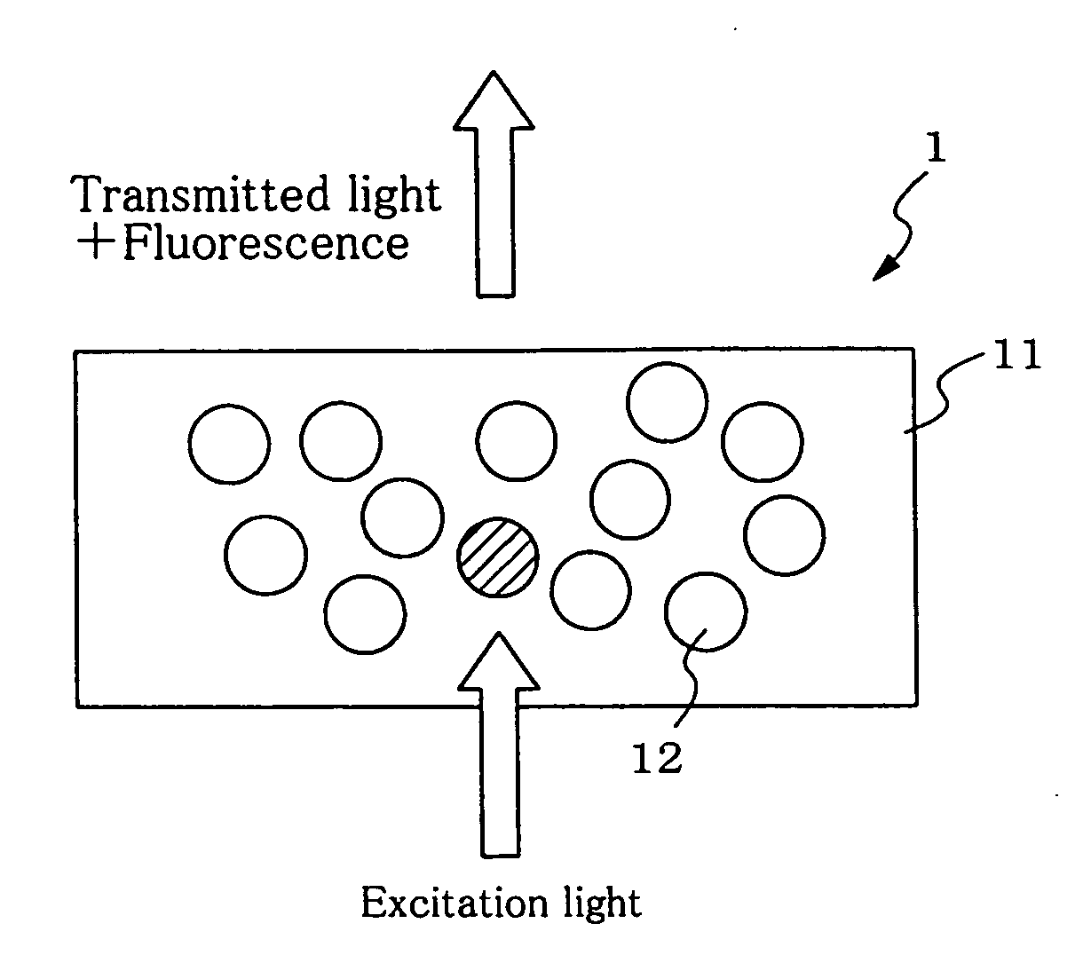
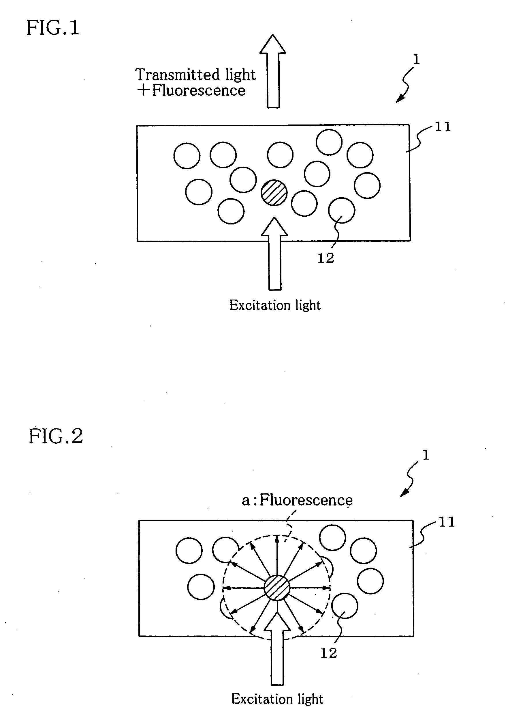
[0057]FIG. 1 is a schematic view showing the cross section of the fluorescent conversion medium.

[0058] A fluorescent conversion medium 1 is a film in which fluorescent particles 12 are dispersed in a transparent medium 11. The fluorescent conversion medium 1 absorbs excitation light from a light source (not shown) and isotropically emits light (fluorescence) having a wavelength longer than that of the light from the light source.

[0059]FIG. 2 is a schematic view showing the state in which a fluorescent particle isotropically emits fluorescence.

[0060] In FIG. 1, the fluorescent particle indicated by the slanted lines absorbs excitation light to isotropically emit fluorescence.

[0061] The light (fluorescence) converted by the fluorescent conversion medium 1 and the excitation light which has passed through the film without being converted are emitted to the outside o...

second embodiment

[0117] A color light emitting apparatus which is a second embodiment of the invention will be described below.

[0118]FIG. 8 is a diagram showing a color light emitting apparatus according to the second embodiment of the invention.

[0119] A color light emitting apparatus 100 includes a light source part 2 which emits visible light and a fluorescent conversion part 10 which receives light from the light source part 2 to emit a fluorescence having a longer wavelength. In this embodiment, the fluorescent conversion part 10 is the same as the fluorescent conversion medium of the first embodiment mentioned above.

[0120] As the light source part 2, there can be used a part which emits visible light. For example, an organic EL device, inorganic EL device, semiconductive light-emitting diode and fluorescent display tube can be used. Of these, preferred is EL device wherein a transparent electrode is provided on the light-outcoupling side. As specific preferable examples of such an EL device,...

third embodiment

[0157]FIG. 10 is a diagram showing a color light emitting apparatus according to a third embodiment of the invention.

[0158] A color light emitting apparatus 101 includes a light source part 2 which emits visible light and a fluorescent conversion part 10 which receives light from the light source part 2 to emit a fluorescence having a longer wavelength.

[0159] The fluorescent conversion part 10 is a multilayer structure of the fluorescent conversion medium 1 of the first embodiment and a color filter 3 which transmits a fluorescent component from the fluorescent conversion medium and cuts off the other light components.

[0160] The color filter 3 prevents a decrease in contrast ratio of the apparatus. The contrast ratio is a brightness ratio of the emitting state where the emitting apparatus 101 receives light from the outside, e.g., sunlight and room lighting, so that the fluorescent conversion medium 1 emits a fluorescence, to the non-emitting state.

[0161] Examples of materials f...


PUM


Abstract

A fluorescent conversion medium including: fluorescent particles including semiconductor nanocrystals, the particles absorbing visible light to emit fluorescence of a different wavelength, and a transparent medium holding the fluorescent particles dispersed therein, and satisfying 0.4<C·d / r3<5.0 wherein r is the average diameter (unit: nm) of the fluorescent particles, d is the film thickness (unit: μm) of the fluorescent conversion medium, and C is the volume ratio (unit: vol %) of the fluorescent particles to the fluorescent conversion medium.

Description

TECHNICAL FIELD [0001] The invention relates to a fluorescent conversion medium and a color light emitting apparatus using the fluorescent conversion medium. More particularly, the invention relates to a highly efficient fluorescent conversion medium in which semiconductor nanocrystals are dispersed, and a color light emitting apparatus using the fluorescent conversion medium and a light source which emits visible light. BACKGROUND ART [0002] A fluorescent conversion medium which converts the wavelength of light from a light source using a fluorescent material has been used in various fields including the electronic display field. [0003] For example, an electroluminescent (hereinafter may be abbreviated as “EL”) device has been disclosed which includes an organic electroluminescent material section which emits blue light or blue green light, and a fluorescent material section which absorbs light from the emitting layer and emits visible fluorescence of at least one color ranging fro...

Claims


Application Information

Patent Timeline
IPC IPC(8): H01J1/62
CPCC09K11/02C09K11/06C09K11/70H05B33/14C09K2211/1007C09K2211/1014H01L27/322C09K11/883H10K59/38
Inventor KUMA, HITOSHI
Owner IDEMITSU KOSAN CO LTD
Why Eureka
Try Eureka