Injection Molded Case for Optical Storage Discs

Inactive Publication Date: 2007-07-19
ENCORE HLDG
View PDF13 Cites 13 Cited by
  • Summary
  • Abstract
  • Description
  • Claims
  • Application Information

AI Technical Summary

Benefits of technology

[0008] One object of the present invention is to provide a one-piece, injection molded optical disc case that has a more aesthetically appealing appearance with rounded rimwalls. Another object of the present invention is to provide a one-piece, injection molded optical case that offers a convenient place to accommodate a title band for displaying indicia of the disc format or other information pertaining to the disc it contains. Optionally, the optical disc case of the present invention includes security features that hamper removal of a packaged optical disc from its case before by shoplifters.
[0010] In another embodiment of the present invention, the optical disc case has an off-center disk mounting hub which is advantageous in two respects. First, the polypropylene sleeve (or PP sleeve) which surrounds and covers major portions of spine and front and rear covers and in which is inserted a printed paper title and credits page, has been set back from the upper edge of the case an amount sufficient to leave a band on which indicia such as “HD DVD” or “Blu-ray Disc” can be printed on the front cover. Second, for the off-center disk mounting hub and platform can conveniently provide space inside the case, either above or below the disk mounting platform for an Electronic Article Surveillance (EAS) tag, without encroaching on the title band at the top of the case.
[0012] In another embodiment, the optical disc case optionally stores a pair of optical discs in a parallel, axially-aligned relationship. One of the problems associated with the storage of two discs on axially aligned hubs is that if the case is compressed in the hub region, the hub release mechanism on each hub will be activated and each hub will release the optical disc that is installed thereon. This problem can be solved by reducing the number of hub release fingers from six to three and then rotating one of the hubs so that the hub fingers of one hub are offset from the hub fingers of the other hub. In addition, the release button on each hub has been recessed so that they cannot push against one another even when the case is compressed. A printed insert may also be stored in the case between the two optical discs, insert support rails are provided on the inside of the front cover. The support rails and the disk mounting hub located on the inner surface of the front cover cooperate to elevate the printed insert above the upper surface of the optical disc that is stored on the hub that is integrated into the front cover. Because the disk mounting hub and platform structure on each cover is offset from the cover centers, the lower support rail is partially incorporated in the front cover disk mounting platform.
[0014] In another embodiment, the optical disc case incorporates a pair of projections which extend vertically from the rear cover vertical near the closure edge, further making it difficult to slide a disc out of the closure side of the case when it is opened just a crack. As an additional security feature, the case can be equipped with at least one, preferably two, security latches that lock the front and back covers together along their closure edges, and can be taped over to slow down shoplifters, thereby making it more difficult to open the case, especially when wrapped in a heat-sealed sheet of transparent display wrap. The latches do not detract from the aesthetic quality of the case, as they conform to the shape of the case when closed and locked.

Problems solved by technology

In addition, as DVDs are considered to be more fragile than CDs, DVD case specifications require a disc retaining mechanism (usually called a hub) having a push-button release.
A serious problem associated with the designs of current DVD cases is that the video disc stored within the case can be stolen without fully opening the case.

Method used


Image

  • Injection Molded Case for Optical Storage Discs
  • Injection Molded Case for Optical Storage Discs
  • Injection Molded Case for Optical Storage Discs

Examples


Embodiment Construction

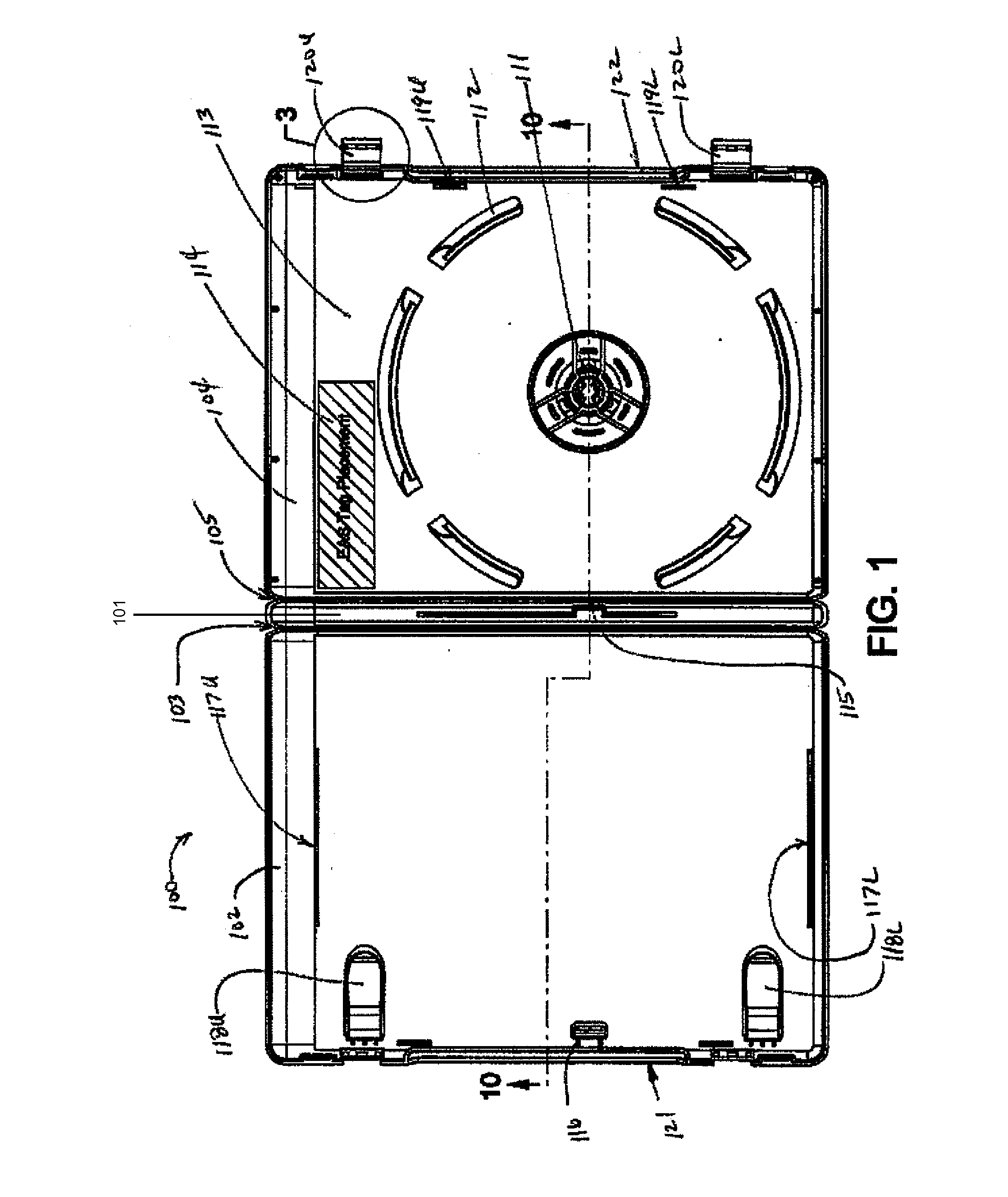
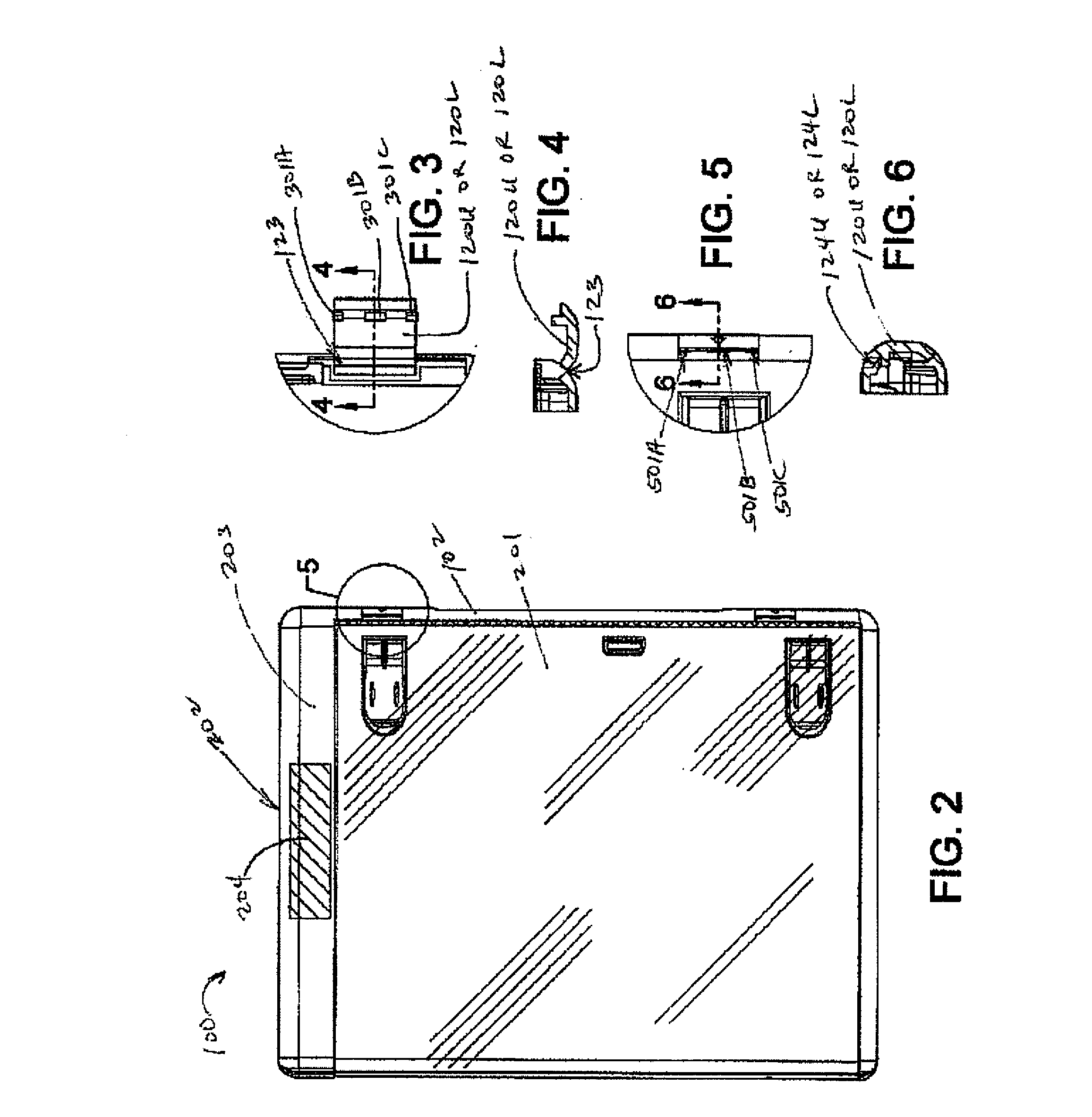
[0026] Referring now to a particular embodiment shown in FIG. 1, a new injection-molded optical disc case 100 has a more modern, aesthetically appealing appearance, and can be used with existing packaging equipment at optical disc packaging facilities. As with conventional DVD cases, the new optical disc case 100 includes a spine 101, a front cover 102 coupled to the spine 101 via a first live hinge 103, and a back cover 104 coupled to the spine 101 via a second live hinge 105. The new DVD 100 case differs from conventional optical disc cases in that, when in a closed configuration, it forms generally semi cylindrical rimwalls, including an upper rimwall 106, a lower rimwall 107, a spine rimwall 108 (FIG. 8), and a closure rimwall 109 (FIG. 9), which intersect in generally quarter-spherical corners 110A, 110B, 110C and 110D (FIG. 7 and FIG. 8), which may comprise some small flattened areas. FIGS. 7-10 also show an optional feature: a flattened band is running along a center portion ...


PUM

PropertyMeasurementUnit
Heightaaaaaaaaaa
Areaaaaaaaaaaa
Transparencyaaaaaaaaaa

Abstract

An injection molded one-piece optical disc case with a front cover and a back cover attached to a spine via live hinges. The case, when closed, has generally semi-cylindrical rimwalls, including upper and lower rimwalls, a spine rimwall, and a closure rimwall. The rimwalls intersect in generally quarter-spherical comers. The generally semi-cylindrical rimwalls may be optionally flattened slightly to prevent multiple closed cases that are being pushed down an assembly line from climbing over one another. Another novel feature of the optical disc case is an off-center disk mounting hub on each cover to leave room for a title band at the top of the case and also to leave room for the attachment of an EAS tag inside the case. The case also optionally incorporates antitheft elements.

Description

CROSS REFERENCE TO RELATED APPLICATIONS [0001] This application is continuation-in-part of application Ser. No. 11 / 268,205, filed Nov. 07, 2005 and this application further claims priority to U.S. Provisional Application Nos. 60 / 760,873, filed Jan. 20, 2006; 60 / 795,504, filed Apr. 28, 2006; and 60 / 797,107, filed May 2, 2006. The contents of the provisional and parent applications are hereby incorporated by reference.FIELD OF THE INVENTION [0002] This invention relates to cases for optical storage discs such as compact discs and digital video discs and, more particularly, to injection molded cases with a title band and off-center disk mounting hub. BACKGROUND OF THE INVENTION [0003] Cases for storing optical storage discs, such as compact discs (CDs) and video compact discs (VCDs) and digital video discs (DVDs), when not being used, have been manufactured for over two decades. The typical case is a square-cornered box having a center hub for receiving the central mounting aperture of...

Claims


Application Information

Patent Timeline
IPC IPC(8): B65D85/30
CPCG11B33/0427
Inventor OSBORN, WARREN R.DUNFORD, BRYAN P.
Owner ENCORE HLDG
Why Eureka
Try Eureka