
Head detecting apparatus, head detecting method, and head detecting program

a head detecting and head technology, applied in the field of head detecting apparatus, head detecting method, and head detecting program, can solve the problems of difficult recognition of the head, reduced accuracy of extraction of moving objects, and difficulty in determining the correct waisted portion of outlin

Inactive Publication Date: 2007-07-12
IBM CORP
View PDF6 Cites 30 Cited by
  • Summary
  • Abstract
  • Description
  • Claims
  • Application Information

AI Technical Summary

Benefits of technology

[0017] According to the present invention, an ellipse can be appropriately applied to a person's head regardless of the accuracy of an extracted foreground region.

Problems solved by technology

The method described in Non-patent Document 1 has a problem such that recognition of the head is difficult when accuracy of the extracted moving object is reduced because of the characteristics of the image or the background, since a waisted portion of the outline was not detected.
For example, if the background includes colorful and complicated texture, since the outline of the moving object is not smooth but has lots of dents, it is difficult to determine the correct waisted portion of the outline by using this method.
Also, for example, in the case in which both hands are put on the head, or in the case in which a person is wearing high collared clothes, dents appear in places other than the intended place, it is difficult to determine the correct waisted portion of the outline by using this method.
Also, in these methods, it is not possible to obtain stable matching results when the outline is not smooth.
Also, in the methods disclosed in Patent Document 4, 5, and 6, it is difficult to recognize the head of a person when the outline is not smooth.
The devices disclosed in Patent Document 7, 8, 9, 10, and 11 are not capable of detecting motion of a head, in the case in which it is difficult to recognize each part of a face due to low resolution of the image, in the case in which a person's face is turned away from the image pick-up side of a camera by more than 90 degree, and the like.
With regard to the device for detecting optical flow described in Patent Document 12, it is possible to compute this when the moving image is obtained under good conditions, such as using an in-vehicle camera, however, it is not possible to compute this when the face is small, when characteristic parts such as eyes, a nose, and the like, cannot be extracted as the person is facing obliquely away from the image pick-up side, or when the background is colorful and its texture is complex, and the like.
In the devices disclosed in Patent Document 13 and 14, a problem about what angle of the interval the data should have arises when the data is prepared.
When the interval of the angle is small, matching takes a long time, and when the angle of the interval is large. the accuracy of detection deteriorates.
Also, incorrect detection occurs due to the difference between a prepared face image and an input face image.
Furthermore, the matching accuracy also deteriorates when a person is wearing glasses, a hat, and the like.
Furthermore, the matching accuracy with the prepared date deteriorates when the extracted moving object is rough due to the characteristics of the image and the background.
As described above, in the conventional techniques, accuracy of recognition of a head and estimation of motion of a head are not good if the contour is not smooth due to the deteriorated accuracy of extracting a person's image.
For example, in the conventional techniques, under the condition in which a monitoring camera is installed in the store of retailer, the outline of a person can not be extracted since the background (shelves for goods) is colorful and its texture is complex.

Method used


Image

  • Head detecting apparatus, head detecting method, and head detecting program
  • Head detecting apparatus, head detecting method, and head detecting program
  • Head detecting apparatus, head detecting method, and head detecting program

Examples


Embodiment Construction

[0035] Hereinafter, the present invention is described through an embodiment of the present invention. The embodiment described below does not limit the scope of claims, nor may all the combinations of the characteristics described in the embodiment always be necessary as means for solving problems of the present invention.

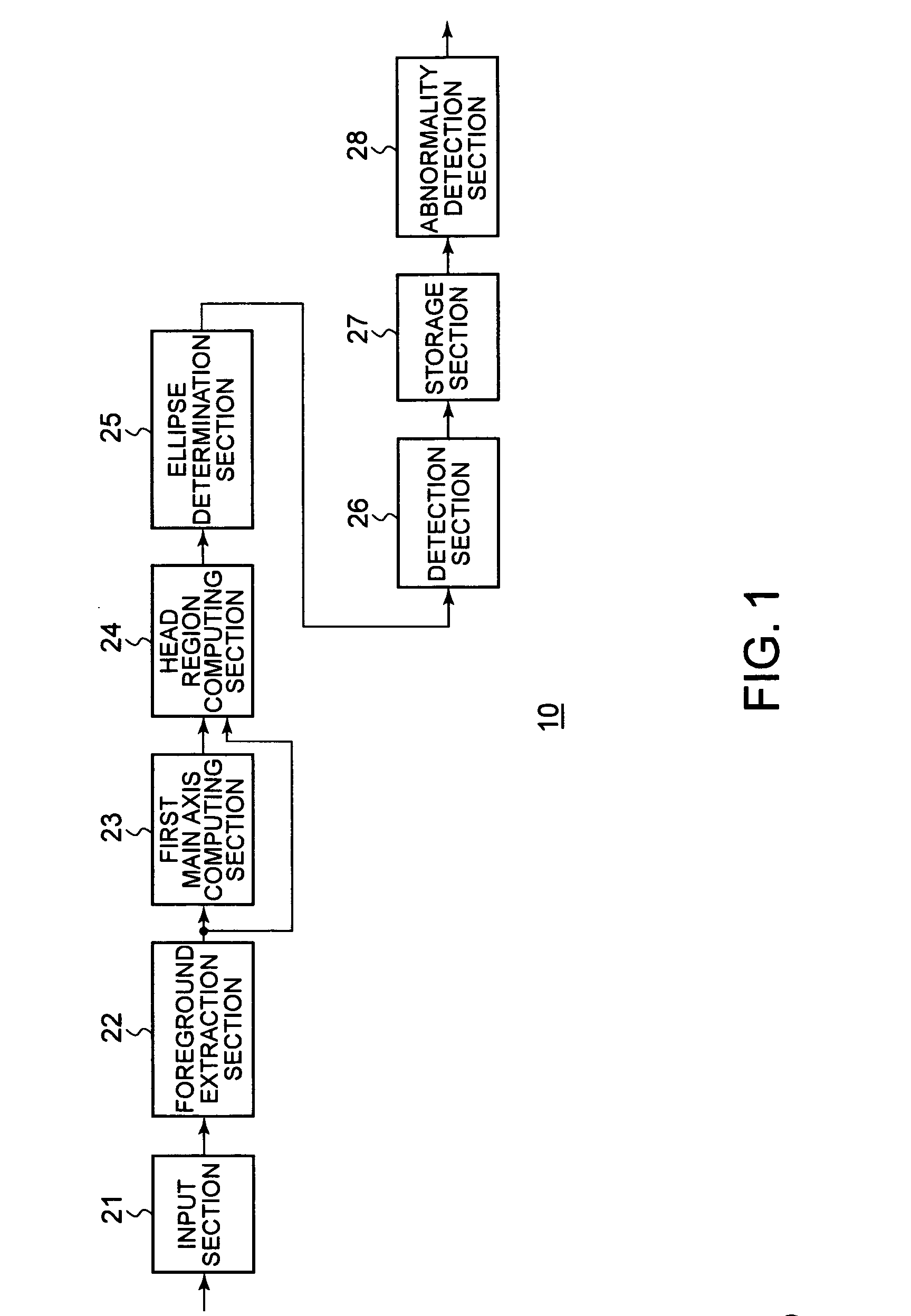
[0036]FIG. 1 shows a configuration of a monitoring system 10 according to this embodiment of the present invention. The monitoring system 10 includes an input section 21, a foreground extraction section 22, a first main axis computing section 23, a head region computing section 24, an ellipse determining section 25, a detection section 26, a storage section 27, and an abnormality detection section 28. The monitoring system 10 extracts an image of a person included in an input image taken by a video camera, or the like, applies an ellipse to the head, and estimates motion of the head based on the motion of the applied ellipse. The monitoring system 10 can appropri...


PUM


Abstract

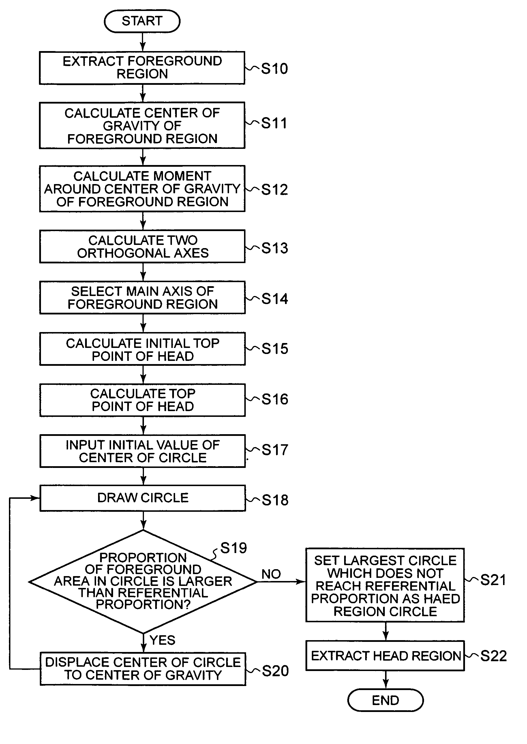
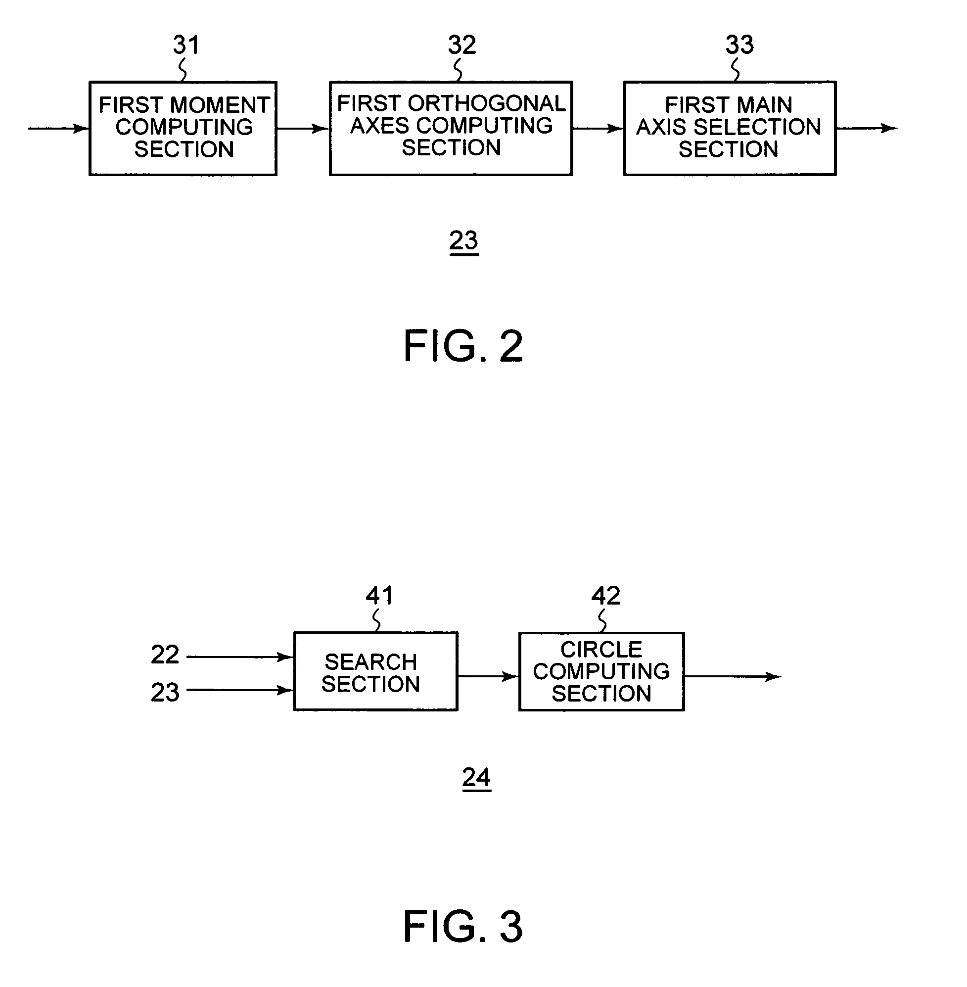
A head detecting apparatus, including a foreground extraction section for extracting a foreground region in which a person is captured from an input image; a first main axis computing section which includes a first moment computing section for computing a moment around a center of gravity of the foreground region and calculating a main axis of the foreground region based on the moment around the center of gravity of the foreground region; a head computing section for computing a head region included in the foreground region as a part thereof based on the main axis of the foreground region and a shape of the foreground region; and an ellipse determining section for determining an ellipse to be applied to a person's head based on a shape of the head region.

Description

FIELD OF THE INVENTION [0001] The present invention relates to a head detecting apparatus, a head detecting method, and a head detecting program. In particular, the present invention relates to a head detecting apparatus, a head detecting method, and a head detecting program which applies an ellipse to the head of person in an input image. BACKGROUND OF THE INVENTION [0002] With evolution of an image capturing apparatus and development of an image processing technique in recent years, it is desirable to automatically analyze and utilize moving images. There is a possibility that in techniques analyzing moving images, estimation of motion of an image-captured person is useful in many application fields such as a monitoring camera, a robot vision, or the like where human beings are involved. When estimating motion of a person, the movement of a head of a person including a face is extremely important information. Techniques for estimating motion of the head of a person by recognizing ...

Claims


Application Information

Patent Timeline
IPC IPC(8): G06K9/00
CPCG06K9/00241G06V40/164
Inventor ISHIKAWA, HIROSHIMAEDA, JUNJINAKANO, HIROKI
Owner IBM CORP
Learn More