
Rebar chair with depth gauge

a technology of depth gauge and rebar chair, which is applied in the field of rebar chair with depth gauge, combined rebar chair and depth gauge, which can solve the problem of not providing any means to ensure the minimum required

Inactive Publication Date: 2007-07-12
PETERSON DAVID J JR
View PDF11 Cites 18 Cited by
  • Summary
  • Abstract
  • Description
  • Claims
  • Application Information

AI Technical Summary

Benefits of technology

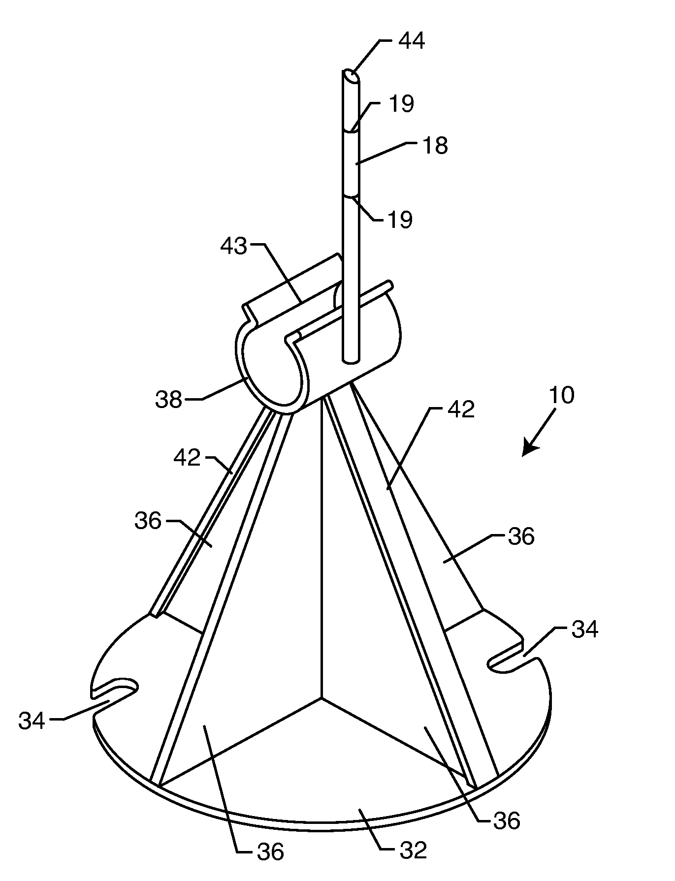
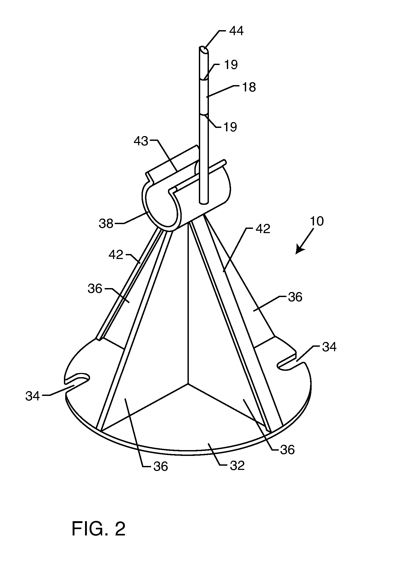
[0010] The combined rebar chair and depth gauge is adapted for economical construction from a lightweight and non-corrosive material such as molded plastic. The device can be color-coded according to different standard sizes, i.e., according to different standard outboard-side and inboard-side spacing dimensions. Alternately, the elongated gauge rod can be provided with distance measure markings along the length thereof, and adapted for suitable length reduction by cutting or breaking to provide the desired inboard-side spacing dimension.

Problems solved by technology

However, such spacer elements have not provided any means for assuring the requisite minimal spacing between the embedded steel and the inboard side of the concrete shell structure.

Method used


Image

  • Rebar chair with depth gauge
  • Rebar chair with depth gauge
  • Rebar chair with depth gauge

Examples


Embodiment Construction

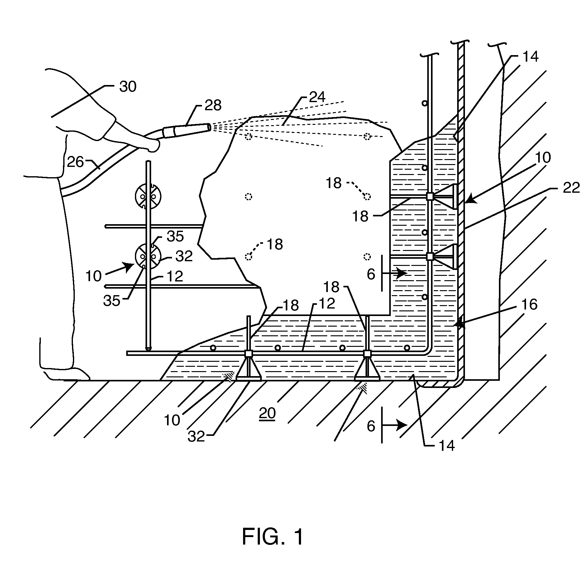
[0019] As shown in the exemplary drawings, an improved rebar chair referred to generally by the reference numeral 10 in FIG. 1 is provided for supporting a grid or cage 12 of reinforcing steel (rebar) in a predetermined position within an open-sided mold or form 14 of the type used, e.g., for constructing a concrete shell structure 16 for a swimming pool or spa or the like. The rebar chair 10 supports the reinforcing steel with a predetermined minimum spacing from a closed side of the form 14, thereby assuring a predetermined minimum concrete wall thickness between the steel and an outboard side of the concrete shell structure 16. In addition, and in accordance with a primary feature of the invention, the rebar chair 10 further includes a rod-shaped depth gauge 18 for assuring a predetermined minimum concrete wall thickness between the steel and an inboard side of the concrete shell structure 16.

[0020]FIG. 1 generally depicts the open-sided mold or form 14 of a type commonly used i...


PUM

PropertyMeasurementUnit
surface areaaaaaaaaaaa
depthaaaaaaaaaa
lengthaaaaaaaaaa

Abstract

A combined rebar chair and depth gauge supports reinforcing steel within an open-sided mold or form, with controlled spacing from outboard and inboard sides of a resultant formed concrete shell structure, e.g., a concrete shell for a swimming pool. The rebar chair has a broad base seated against a closed side of the form defined by soil or a wooden form structure. At least one gusset projects from the base and carries a support member for receiving and supporting a reinforcing steel bar with predetermined spacing from the form. A rod-shaped depth gauge projects a predetermined distance beyond the support member. In use, the concrete shell structure is formed by spraying concrete material against the form until a free end of the depth gauge is covered, thereby insuring a predetermined minimum spacing between an inboard side of the shell structure and the reinforcing steel supported therein.

Description

BACKGROUND OF THE INVENTION [0001] This invention relates generally to improvements in so-called rebar chairs for supporting reinforcing steel within a concrete structure such as a concrete shell for a swimming pool or the like. More particularly, this invention relates to a combined rebar chair and depth gauge for supporting reinforcing steel within an open-sided mold or form, with controlled spacing from outboard and inboard sides of a resultant formed concrete shell structure. [0002] In-ground swimming pools and spas are commonly constructed with a steel-reinforced concrete shell structure. In this regard, in accordance with conventional pool / spa construction methods, a suitable hole is excavated to define an open-sided mold or form defining an outboard surface of the to-be-formed concrete shell structure. In a typical construction technique, floor area portions of this open-sided form may be defined directly by the excavated soil, whereas generally vertical wall portions are nor...

Claims


Application Information

Patent Timeline
Patent Type & Authority Applications(United States)
IPC IPC(8): E04C5/16
CPCE04C5/20
Inventor PETERSON, DAVID J. JR.
Owner PETERSON DAVID J JR
Learn More