Self-cleaning filtration nanofiber membrane

a technology of nanofiber membranes and filtration membranes, which is applied in the direction of membranes, filtration separation, separation processes, etc., can solve the problems of damage to the membrane, unworkable standard filter cleaning methods, and small porous size of these membranes, and achieve the effect of easy flushing from the membran

Inactive Publication Date: 2007-07-05
CEO ESPINEX
View PDF7 Cites 24 Cited by
  • Summary
  • Abstract
  • Description
  • Claims
  • Application Information

AI Technical Summary

Benefits of technology

The patent describes a membrane that can clean itself using microfibers and nanofibers that contain special particles. These particles can break down organic molecules when exposed to UV light, making it easy to flush them from the membrane. The special particles are titania nanoparticles, which are located on or near the outside of the fibers. The technical effect of this invention is a self-cleaning membrane that can effectively clean itself without needing additional chemicals or equipment.

Problems solved by technology

The patent text discusses the use of nanofibers and microfibers in membrane filters for filtration applications. However, these membranes can easily become fouled with filtered organic molecules, making them difficult to clean using standard methods. The technical problem is how to effectively clean these membranes without damaging them.

Method used


Image

  • Self-cleaning filtration nanofiber membrane
  • Self-cleaning filtration nanofiber membrane
  • Self-cleaning filtration nanofiber membrane

Examples


Embodiment Construction

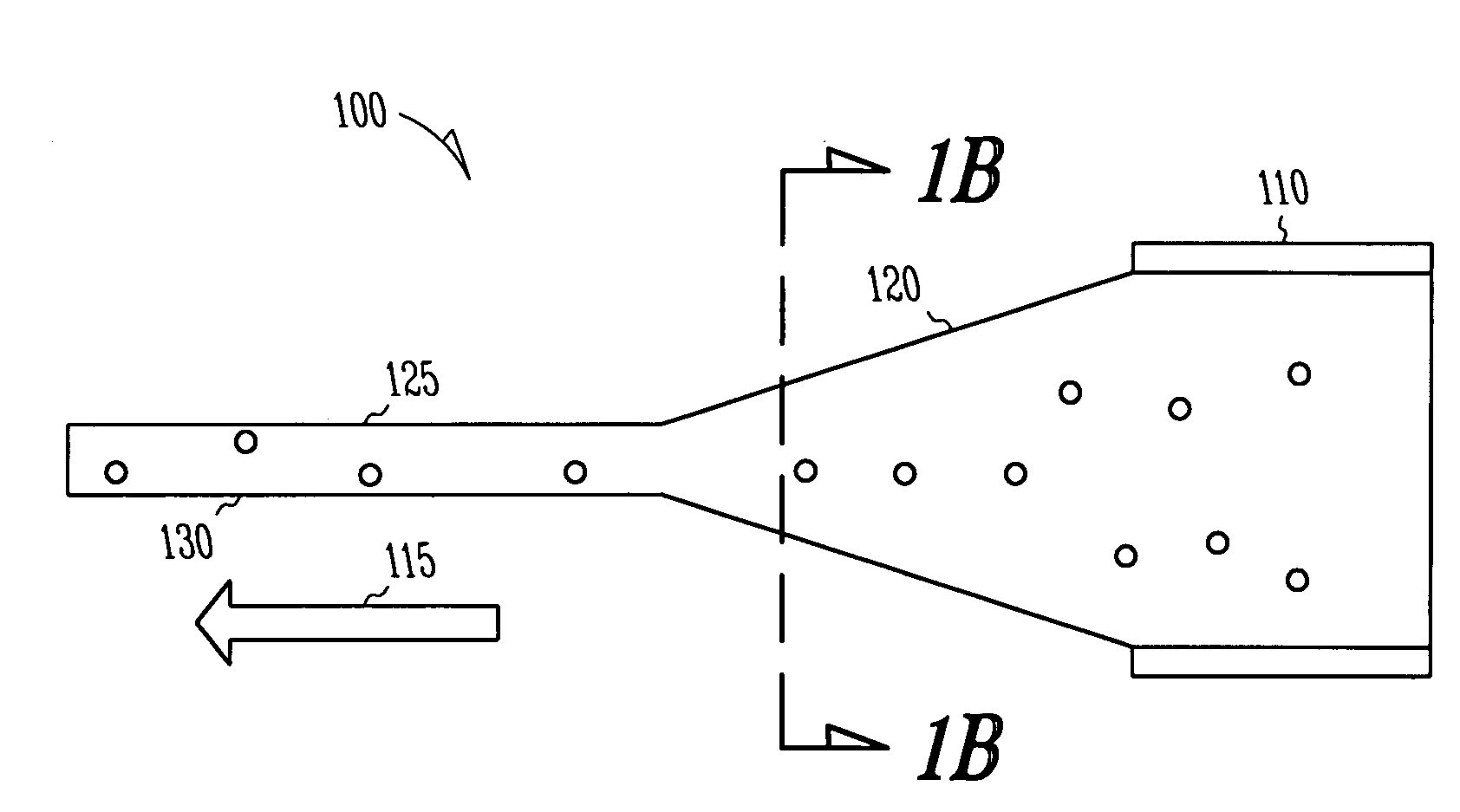
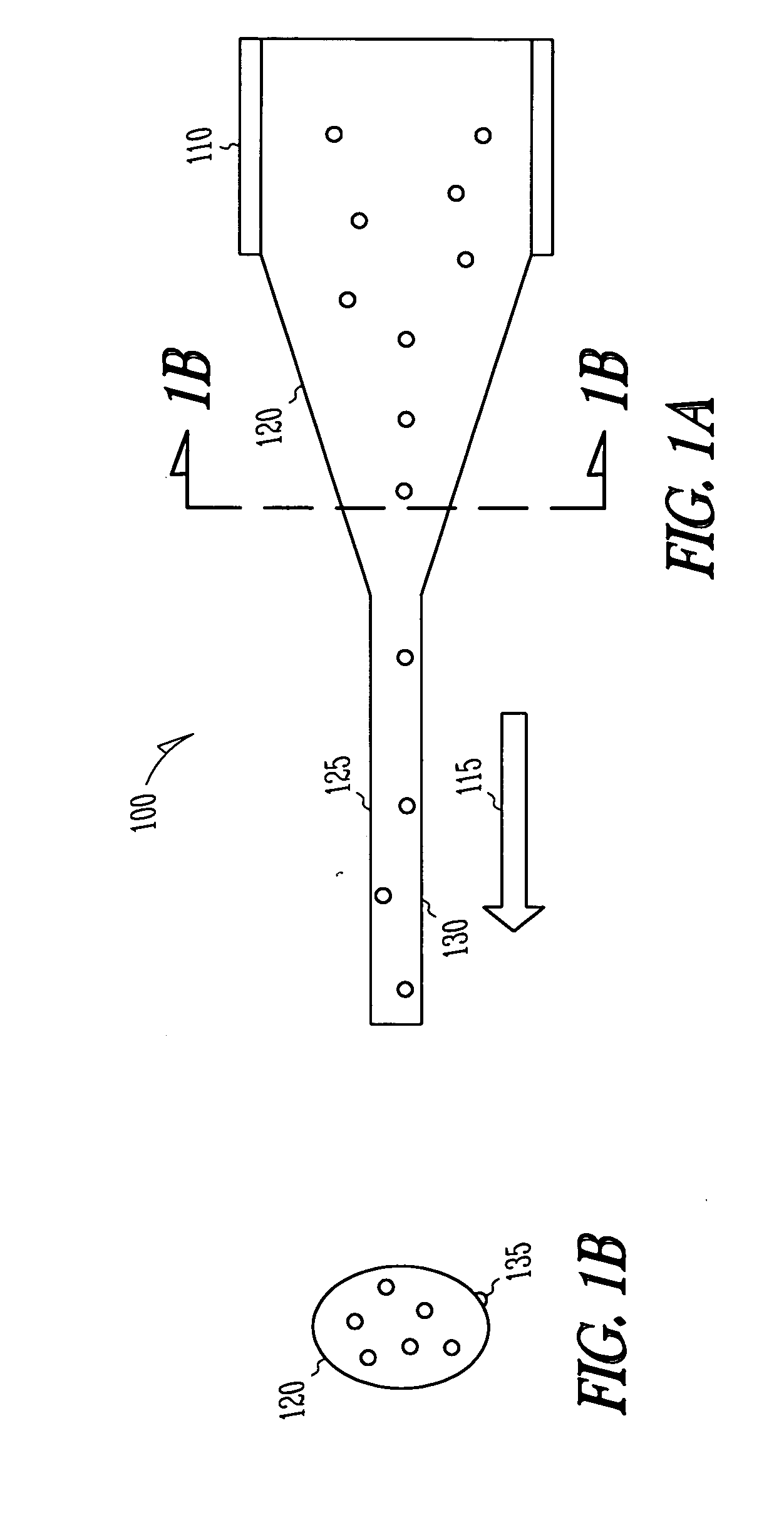
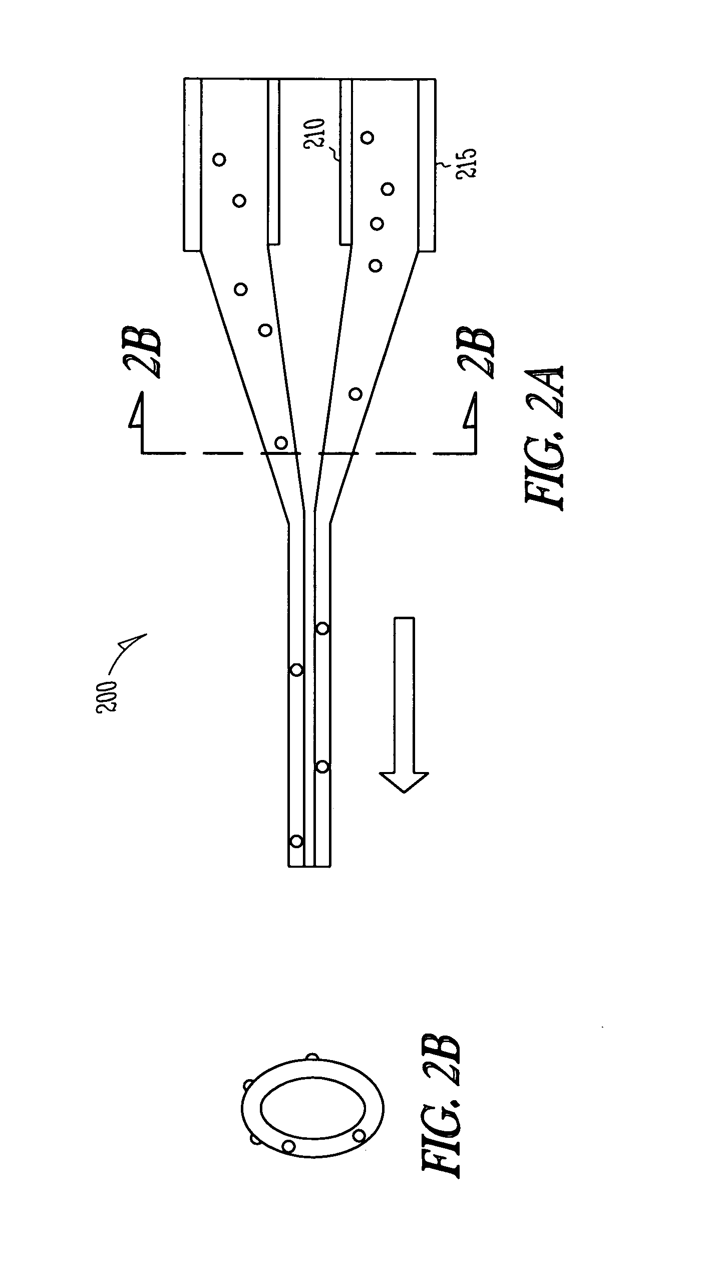
[0012] In the following description, reference is made to the accompanying drawings that form a part hereof, and in which is shown by way of illustration specific embodiments in which the invention may be practiced. These embodiments are described in sufficient detail to enable those skilled in the art to practice the invention, and it is to be understood that other embodiments may be utilized and that structural, logical and electrical changes may be made without departing from the scope of the present invention. The following description is, therefore, not to be taken in a limited sense, and the scope of the present invention is defined by the appended claims.

[0013] A self-cleaning nanofiber membrane extends usage life span of filters by decomposing adsorbed molecules. In one embodiment, the diameter of the fibers is less than 100 nm and photo-catalytic nanoparticles are embedded on their surface. They were fabricated by electrospinning technique by electrostatically extruding po...


PUM

PropertyMeasurementUnit
Diameteraaaaaaaaaa
Diameteraaaaaaaaaa
Nanoscale particle sizeaaaaaaaaaa

Abstract

A self-cleaning membrane is formed of microfibers and/or nanofibers that contain functionalized nanoparticles. In one embodiment, the nanoparticles contain photo-catalytic particles, that when exposed to ultraviolet light, cause decomposition of organic molecules. The decomposed molecules may be easily flushed from the membrane. In one embodiment, the particles are titania nanoparticles, some of which are disposed on or near the outside of the fibers.

Description


Claims


Application Information

Patent Timeline
Owner CEO ESPINEX
Why Eureka
Try Eureka