
Dishwasher

a technology for dishwashers and washing machines, applied in the field of dishwashers, can solve problems such as troublesome users in making necessary settings for dishwashers, and achieve the effect of high level of washing and rinsing performan

Inactive Publication Date: 2007-07-05
SANYO ELECTRIC CO LTD
View PDF2 Cites 47 Cited by
  • Summary
  • Abstract
  • Description
  • Claims
  • Application Information

AI Technical Summary

Benefits of technology

The present invention provides a dishwasher that can exhibit high levels of washing and rinsing performance even when using a common kitchen detergent. The dishwasher has a wash chamber for containing the dishes and a washing means for drawing water from the bottom of the wash chamber and spraying it onto the dishes. The dishwasher has a detergent selector for determining whether the detergent is a dedicated detergent or a common kitchen detergent and allowing users to set the detergent type. The dishwasher can selectively carry out one of two operational sequences based on the detergent type: a dedicated operational sequence or a normal operational sequence. The detergent water sprayed from the washing means has a lower average strength in the normal operational sequence to allow for a higher level of washing performance. The operation controller controls the washing means to adjust the strength of the water spray based on the detergent type and the user's needs. This feature improves the usability of the dishwasher and ensures a high level of washing performance even when using a common kitchen detergent.

Problems solved by technology

However, it will be troublesome for users to make necessary settings on the dishwasher according to the type of detergent used.

Method used


Image

  • Dishwasher
  • Dishwasher
  • Dishwasher

Examples


Embodiment Construction

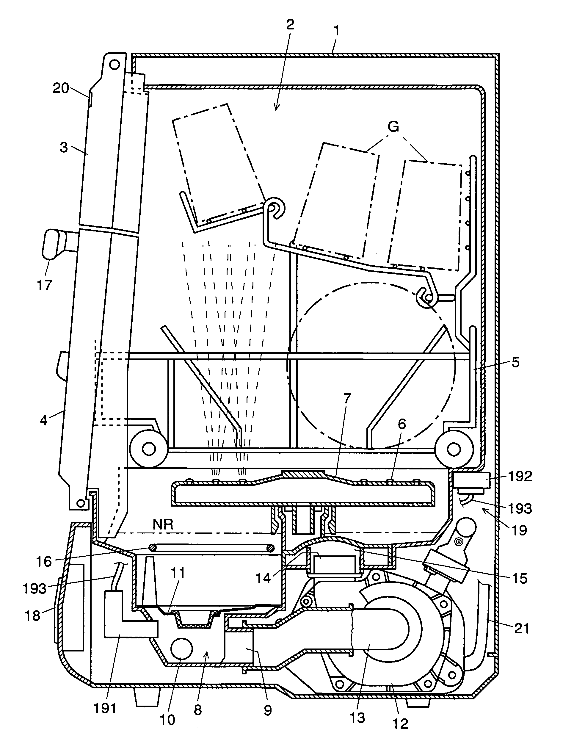
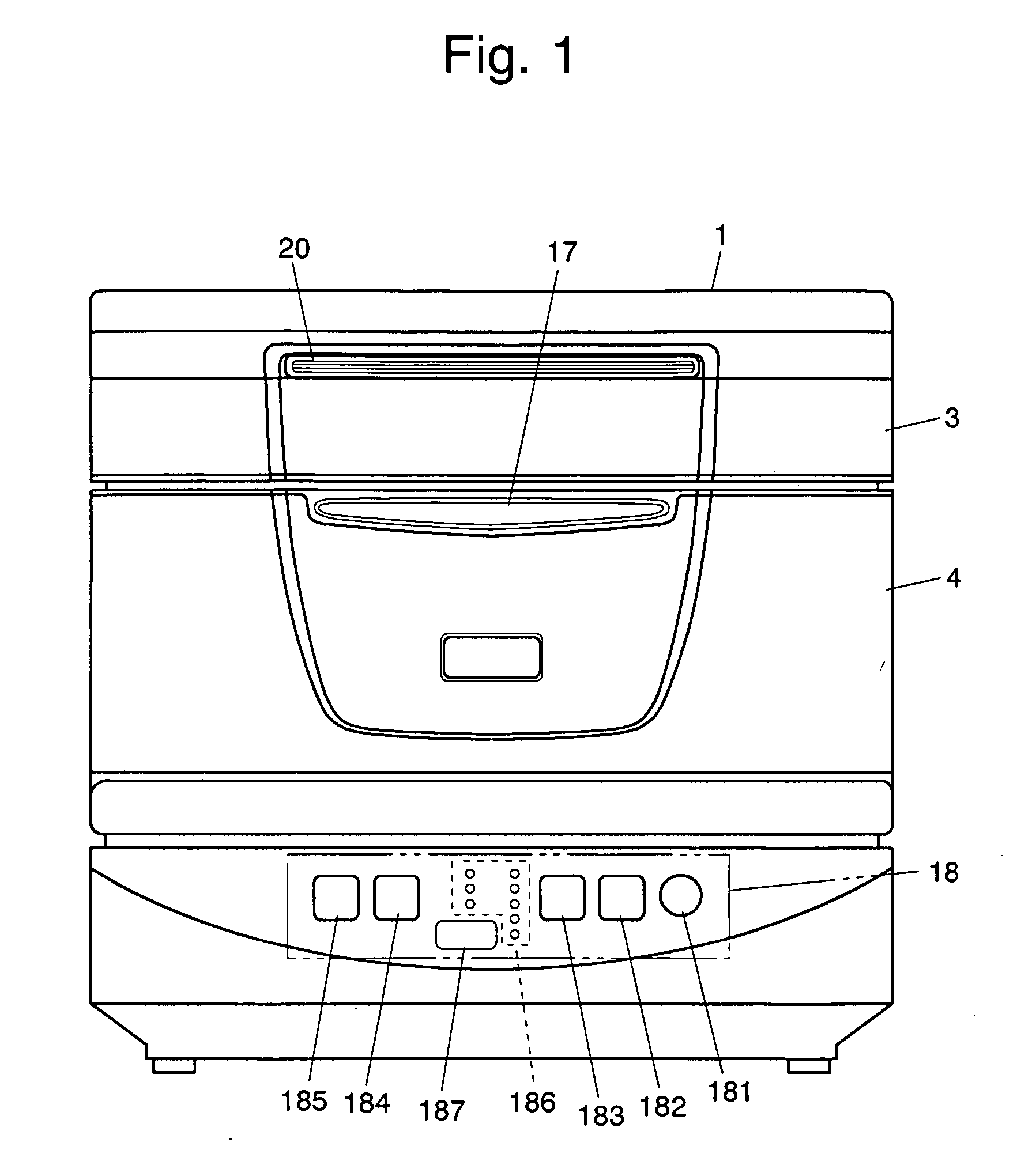
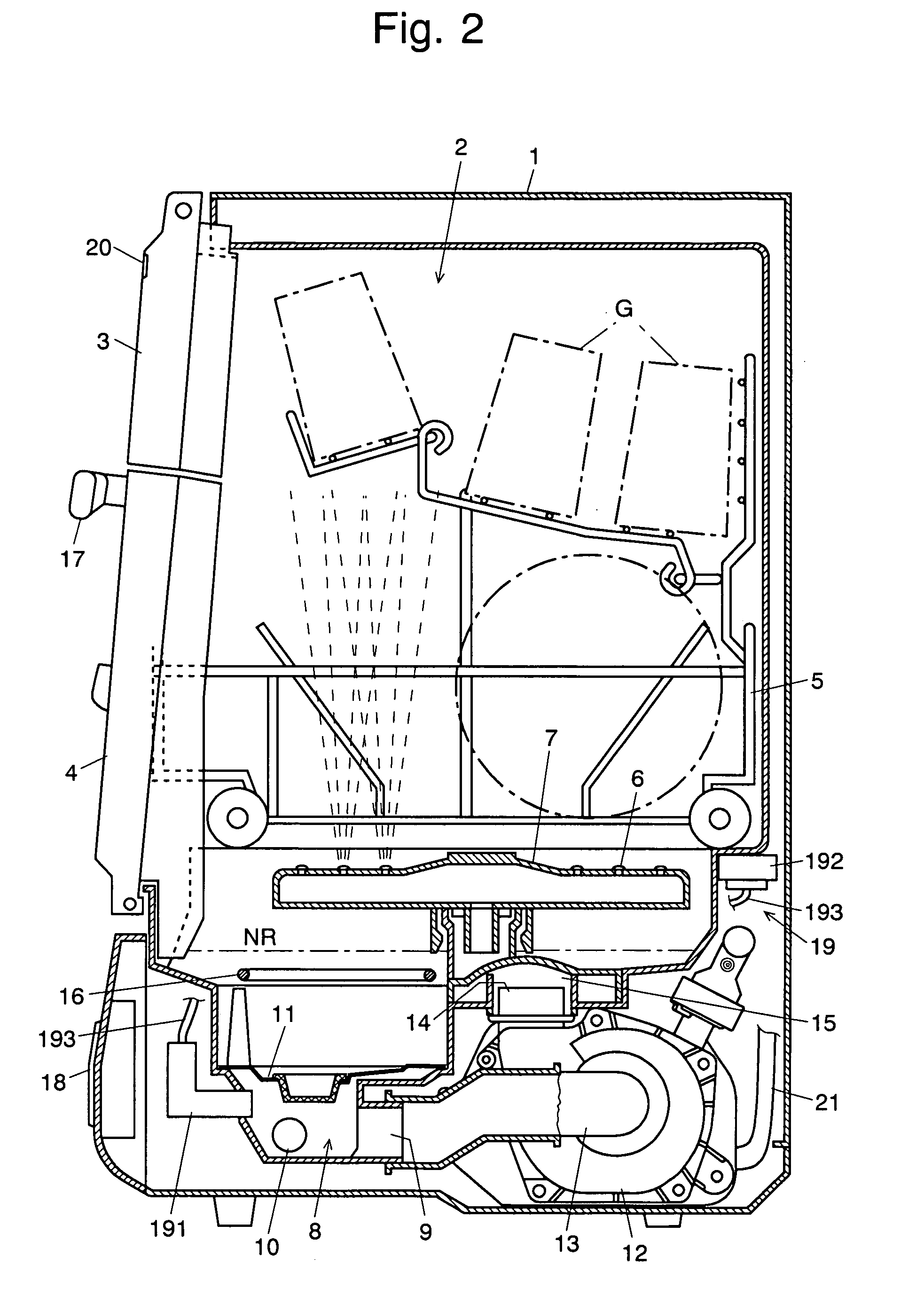
[0083] A dishwasher as an embodiment of the present invention is described with reference to the attached drawings: FIG. 1 is a front view of the dishwasher of the present embodiment, and FIG. 2 is a vertical sectional view of the dishwasher viewed from a side. The present dishwasher is a slim type dishwasher having a small depth so that it can be placed in a small area, such as the top area adjacent to the sink of the kitchen.

[0084] The housing 1 encloses a wash chamber 2, which also serves as a drying chamber. The front opening of the wash chamber 2 is equipped with an upper door 3, which is fixed to a shaft at the upper end, and a lower door 4, which is fixed to another shaft at the lower end. The two doors constitute double doors that swing upwards and downwards. The lower door 4 has a handle 17 located at the center of its upper end. When a user holds the handle 17 and pulls it forward to open the lower door 4, the upper door 3 also opens upwards because the two doors are inte...


PUM


Abstract

The dishwasher according to the present invention has two operation courses: one course adapted for using a low-foaming dedicated detergent; and the other course adapted for using a high-foaming kitchen detergent. In the kitchen detergent course, the dishwashing operation includes a first mode of the “spray and wait” process carried out as a preliminary washing operation, including the steps of spraying the water containing a detergent onto the dishes for a short period of time and subsequently halting the spray for a certain period of time. During this process, the amount of the foam present within the wash chamber is determined by means of a photosensor located within the drying duct. If there is a large amount of foam, a longer period of time is set for draining the detergent water. After the water is drained for the aforementioned period of time, fresh water is supplied to a predetermined level. With the concentration of the detergent water thus regulated, a second mode of the “spray and wait” process is carried out as the main washing operation. For a larger amount of the foam produced in the first “spray and wait” process, the detergent water is diluted to have a smaller concentration, so that the second “spray and wait” process is prevented from producing an abnormally large amount of foam. Thus, the dishwasher is capable of washing the dishes with an inexpensive, easy-to-purchase kitchen detergent while preventing the foam from escaping to the outside.

Description

TECHNICAL FIELD [0001] The present invention relates to a dishwasher for washing dishes and / or utensils by spraying water onto the dishes and utensils contained in a wash chamber. In the present description, the word “dishes” should be interpreted as the “dishes and / or utensils,” if not otherwise specified. BACKGROUND ART [0002] In general, a household dishwasher for washing and rinsing the dishes includes a wash chamber for containing the dishes, a water supply for introducing water into the wash chamber, and a pump for drawing water from the bottom of the wash chamber into a wash arm and for spraying the water from the nozzles of the wash arm onto the dishes. The sprayed water hits the dishes or the inner wall of the wash chamber, and then returns to the bottom of the wash chamber and passes through a filter for removing food particles. The filtered water is drawn again by the pump. [0003] In such a dishwasher, if a common kitchen detergent (which is simply called the “kitchen det...

Claims


Application Information

Patent Timeline
Patent Type & Authority Applications(United States)
IPC IPC(8): B08B3/00A47L15/46A47L15/00A47L15/42A47L15/44
CPCA47L15/0021A47L2501/30A47L15/4244A47L15/4297A47L15/44A47L15/488A47L2301/026A47L2401/026A47L2401/10A47L2401/30A47L2501/04A47L2501/06A47L2501/12A47L2501/20A47L2501/26A47L15/0049A47L15/46
Inventor OMACHI, MASANORIMORISHIGE, MASAKATSUNITO, HIDEYUKISHINMURA, MITSUNORISUZUKI, HAJIMESUO, KIYOYUKI
Owner SANYO ELECTRIC CO LTD
Learn More